Development of the SWIFT
A Tailless Foot-Launched Sailplane
by Ilan Kroo and Eric Beckman
with Brian Robbins, Steve Morris, and Brian Porter
version first published in Hang Gliding Jan. 1991
The SWIFT is a high performance foot-launched sailplane, designed to combine some of the convenience of hang gliders with the soaring performance of sailplanes. It takes off and lands like a hang glider, yet maintains exceptional performance at high speeds, achieving a lift-to-drag ratio of about 25:1. Although it is a fully-cantilevered rigid wing with aerodynamic controls and flaps, it weighs only about 100 lbs and is easily transported on the top of a car. This article summarizes the design, construction, and initial flight testing of this ultralight sailplane.
History
This sailplane represents the marriage of two projects with similar goals undertaken by two groups with different expertise. In January of 1986, Brian Robbins, Craig Catto, and Eric Beckman set out to build a new hang glider with better performance than other gliders available at the time. As BrightStar Hang Gliders, Brian and Eric, with Craig's help, began the development of the Odyssey, a rigid wing hang glider. The Odyssey utilized a molded "D" tube of fiberglass, Kevlar and carbon fiber with aluminum and foam ribs supporting a mylar skin. The first prototype was finished in March of 1986, and a program of flight and vehicle-based testing led to its rapid development over the next two years. Brian Porter joined BrightStar as a team pilot in 1988 and went on to pilot the glider to first place in the 1989 U.S. National Hang Gliding Championships at Dunlap, California. Despite this success, it was apparent that there was much left to be done in the development of high performance rigid wing hang gliders.
Two hours South of BrightStar, at Stanford University, work had been underway since 1985 on the design of a very high performance glider with some of the same objectives as those of the Odyssey project. Ilan Kroo, a professor in the aeronautics department, got Stanford to offer course credit for the preliminary design work and soon a group of graduate students began running a lot of computer programs, generating a lot of paper, and coming up with some interesting aerodynamic design ideas along the way. Although the performance estimates looked impressive and the design became perhaps the world's most thoroughly analyzed glider, time and building experience were in short supply and the Stanford SWIFT design appeared as though it might become just an academic excerise.
Steve Morris, one of the Stanford Ph.D. students, met Brian Porter at a Fly-In at McClure reservoir and soon the "gang of five" gathered at Brian Robbin's house to discuss the Odyssey and the SWIFT and Brian's mother's pizza. Brian thought that perhaps Ilan and Steve could improve the Odyssey's airfoils somewhat; Ilan and Steve thought that Brian might try out the aerodynamic controls to improve hang glider handling. As Brian talked about the Odyssey and Ilan described the aerodynamic design options, it became clear that a radically new design was possible - and Brian could build it. Four months later, in December of 1989, the SWIFT took to the air over a small hill in Marin County.
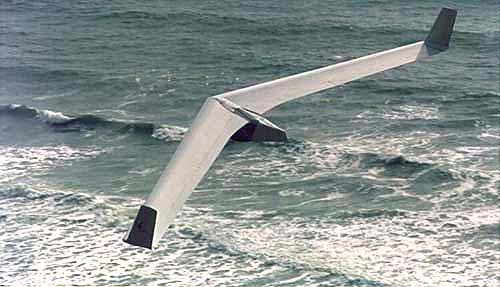
 Figure 1. First prototype.
Aerodynamic Design
Sizing and Performance Limits
The design of the SWIFT began with a study of the requirements for cross-country soaring. Ilan had written an article in a 1982 issue of Hang Gliding Magazine describing what sort of glider would be needed for extended cross-country soaring based on distributions of thermals and interthermal downdrafts measured by Dick Johnson. One of the conclusions of that study was that interthermal glide ratios of at least 15 to 18 in the presence of 0.5 kts of sink was needed to make this kind of soaring easily attainable. At that time, only a dozen 100 mile flights had been made by hang gliders. Today, although flights approaching 300 miles have been made, most pilots (even most advanced pilots) have not flown 100 miles. One of the factors limiting the flight distances of hang gliders is their speed. Thermals are commonly encountered for a rather limited time during daylight hours and with average cross-country cruising speeds of less than 20 kts, one needs to fly for five hours to go 100 miles. Thus, extended cross-country soaring requires not only a good enough glide to make it to the next thermal, but a fast enough glide to get there quickly and in the presence of headwinds or sink. This is easily done by making large span sailplanes with high wing loading. But if the glider is to be foot-launched, it must be light (span not too large) and have a low wing loading. More refined studies of Johnson's data and baragraph records from George Worthington's Mitchell wing flights in the Reno area suggested that a foot-launched sailplane with the required performance was just barely possible. The following target performance figures were established and work began to define the aircraft geometry.
Target Performance for Foot-Launched Sailplane
- Minimum Sink Rate in 100' radius turn: 200 ft/min
- Maximum L/D: 20:1
- L/D at 60kts: 15:1
- Stalling speed: no higher than existing hang gliders for safe foot-launching and landing
- Weight: less than 90 lbs
- Exceptional controllability for safe flight at low speeds
The fourth constraint meant that even with large flaps, the wing area would be 120 to 140 sq ft. With this constraint, the third goal would be very difficult, requiring an unprecedented level of aerodynamic streamlining. To achieve the desired performance, low drag airfoils and an extremely clean pilot fairing would be required. The sink rate polars in figure 2 illustrate the importance of streamlining, especially for light weight gliders at high speed. The figure also shows how the predicted sink rate of the SWIFT compares with other gliders; it is clearly in a class above hang gliders and compares very favorably with the Schweizer 1-26 sailplane at speeds up to about 60 kts.
Figure 2. Performance Comparison
Configuration Studies
Unless one does something very wrong, the performance of a glider is determined primarily by its span, area, and streamlining. The selection of the configuration, whether conventional, canard, tailless, or something else, is based more on issues such as packaging, handling qualities, manufacturability, transportability, etc.. In the development of the SWIFT, several possible configurations were studied. The results indicated very small performance differences between tailless, conventional and canard designs; however, the conventional design suffered some from the short tail length required for landing flair and take-off ground clearance. The directional stability of a slightly-swept canard was poor, and performance was also compromised by the short coupling. The tailless design was statically-balanced, compact, and did not pay the weight penalty that would be associated with a tail boom. (Note that even a 5 lb boom represents more than 5% of the empty weight and a very large fraction of the wing bending weight.)
Some of the well-known disadvantages of tailless aircraft were alleviated by the careful 3-D aerodynamic design of the wing. The combination of sweep, taper, and twist was arranged so that rather conventional airfoil sections with negative pitching moments (not reflexed airfoils) could be used. The penalties associated with too much twist were eliminated by changing the effective twist with trailing edge trim and control surfaces. One of these trim surfaces is a large (45% span) flap. When deflected down for higher lift, the glider noses up slightly and trims at a lower speed. It may be deflected downward as much as 45° for landing and approach, cutting the L/D down to a managable value and slowing the glider down for stand-up landings. This use of the inboard flap surface for pitch trim gives the aircraft its name. At the risk of confusion with the long line of Swift aircraft, including one infamous hang glider and another "rigid" wing recently anounced (Owens Swift), the BrightStar SWIFT stands for Swept Wing with Inboard Flap for Trim.
 Figure 3. SWIFT Layout
Stability and Control
As anyone who has ever tried to fly a very stiff, 38 ft span hang glider will attest, performance is not usable if the glider doesn't handle well. One of the major goals of this project was to provide vastly improved handling qualities to a foot-launched glider, and many of the SWIFT's features are there to improve stability and control. The large tip chord provides additional pitch damping to increase the aircraft's dynamic stability and reduce the possibility of tumbling in extreme conditions. It also gives the elevons increased control authority especially at low speeds. The use of aerodynamic pitch controls (actuated by a side-stick controller) makes it possible to trim the glider over a very large speed range without large stick forces or low stability and gives the pilot positive control in very rough conditions when weight shift would do little good. The stalling characteristics are also improved by the moderate taper, high effective twist, and vortilons - vortex generators originally invented in the development of the DC-9.
The SWIFT's winglets are fixed surfaces, not rudders. They increase the effective span of the wing, but more importantly interact with the ailerons to produce favorable yawing moments and increase the roll control authority. Half-span elevons provide the large roll control moments that could not be achieved with weight shift. These surfaces, in combination with the fixed winglets produce a nicely-coupled rolling and yawing motion without the delay or performance loss associated with drag rudders. The size of the winglets and elevons were determined from computer simulations of the glider's dynamics and from flight tests of two radio-controlled models built by Steve and Ilan.
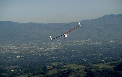 Figure 4. Photo of RC Model over Stanford
Airfoil Development
Airfoils were designed by the Stanford group especially for the SWIFT. The sections have a small negative pitching moment and were designed to operate in the Reynolds number range of 700,000 to 2,000,000. They make use of laminar flow over the first 25% of the chord, if they can get it, but are explicitly designed to experience little performance degradation if the flow is made turbulent by rain or surface irregularities. This amount of laminar flow was selected based on the idea that the first 25% of the airfoil could be quite smooth and accurately constructed. The airfoil thickness at the flap and elevon hingelines was originally quite large to provide strength in this area. Tests on the first prototype suggested that the strength in this region was not a problem, but the gaps created by control deflections added a great deal of drag. The airfoils were redesigned with very thin trailing edges which successfully reduced the control surface gap drag. Except for the analysis of these sections using an airfoil design program on Apple Macintosh and a NASA program, the airfoils were not tested before the first prototype was built. Truck-mounted tests of the glider suggest that the airfoils are working as predicted, but accurate performance verification remains to be done. The airfoil is shown in figure 4, for illustration purposes only. (Scaling this section up from this drawing would be a real mistake.)
Wing Optimization
The final step in the SWIFT's aerodynamic design involved complex trade-offs between wing taper, twist, flap size, flap deflections, elevon deflections, and wing area. Changes that might benefit high-speed performance might hurt thermalling ability or increase stall speed above acceptable limits. The final trade-offs were made by simulating a long cross-coutry flight on the computer and using a numerical optimizer to select the design with the best overall soaring performance. The simulation included thermal models, inter-thermal sink, and a relatively complete aerodynamic analysis (panel model) of the design.
 Figure 5. Vortex Lattice Model of Swift
Structural Design and Construction
The structure of the SWIFT is designed to meet the demanding requirements of very low drag (fully cantilevered, accurate airfoil definition for laminar flow) and light weight. The wing structure uses a D-tube covering the first 25% of the chord with ribs extending from there back to the control surface hinge line at 75% chord. The prototypes were constructed with an Aluminum D-tube and mylar covering to reduce costs and one-off construction time. This made it possible to refine the design before committing to the molds from which production versions will be built. While the prototypes weigh about 100 pounds, production gliders should be substantially lighter with their Kevlar skins and graphite spar caps. The loads that need to be carried by the glider are very large. Because of the low wing loading and high design airpseeds, the effect of gusts is amplified. To comply with FAA sailplane criteria* the glider must be capable of withstanding positive and negative vertical gusts of 24 ft/sec up to VNE. Since the maximum speed of this sailplane is above 60kts, the required limit load is about 6 g's. The prototypes were static loaded to 5 g's to be sure that they could be test flown.
The pilot fairing is another important aspect of the design. Based on Brian Porter's experience with the Voyager and Odyssey, a fully-enclosed fuselage was constructed with 14 mil Lexan surrounding a cage of aluminum tubing. The pilot supports the glider with shoulder straps on the ground and sits in a reclining position in flight, supported by a fabric sling ala Mitchell Wing.
Flight and Vehicle Testing
The first glider was mounted on Brian Robbin's pickup truck, and was instrumented with a load cell to measure total lift. The glider was free in pitch so that stick and elevon positions for trim could be measured. The glider was also covered with yarn tufts so that we could observe where stall first began and adjust the vortilon position if necessary. Apart from some early separation associated with large flap gaps (eliminated in the second prototype), the tests held few surprises and flight testing began in December 1989.
Eric and Brian Porter made the first flights from a 50 foot hillside in Marin County. The elevons made control on the ground very easy as the wing could be rolled easily even in the very light breezes that day. Despite the high wing loading of the first glider, take-off was not difficult and a few test glides showed that the wing was stable and controllable with a glide that wouldn't quit.
Flights at Mt. Tamalpais and Ft. Funston on the Northern California coast soon followed and we learned more about the glider performance and controllability. The first prototype had an excellent glide at high speeds, but with the flaps defelected at low speeds, did not do much better than good flex-wings in terms of minimum sink. Roll response was also not as snappy as Eric would have liked, so we took advantage of a bonked landing to retire the first wing and begin work on a second prototype. The new wing had somewhat larger control surfaces, revised airfoils, improved winglet sections, and a bit less wing area. The first flights at Ft. Funston proved that it was a big improvement.

After 10 or so hours of flying time we were quite happy with the design. It had been flown in relatively turbulent conditions, out-flew all flex wings by a wide margin, and proved to be a pleasure to fly. But coastal ridge sites are one thing, real cross-country conditions are another. So to determine the wing's performance and controllability, we took it to a real cross-country area: the Owens Valley. With a complete pilot fairing, radios and instruments, oxygen system, parachute, and water, the SWIFT took off at a gross weight of over 300 lbs from the 10,000 ft launch at Horseshoe Meadows. Pilots began leaping at about 10 AM, but Eric waited until most others had launched; he was in the air at 11, late by Horseshoe standards. Flying north along the Sierras, he passed most of the conventional gliders. "I'm only getting to 13-5," Eric heard over the radio. "Yeah, no one seems to be getting any higher than that," said another pilot. Eric replied, "I'm at 15-5 and I haven't been circling." Just south of Bishop, Eric and the SWIFT crossed the valley to the White Mountains, passing the first of the hang gliders who had a 1 hour head start. Continuing north passed Boundary Peak, Eric began to feel hypoxic. (We later found an obstruction in the oxygen system.) He decided that he should cut the flight short because of this and began his final glide. When he reached Minas he was stll at 14,000 ft and went looking for sink. Finding a bit, he lowered the flaps to act as drag producing dive brakes and landed. The first Owens Valley SWIFT flight covered about 140 miles. The idea of a true foot-launched sailplane has finally come to pass.

Concluding Comments -- Future Work
Where do we go from here? The basic aerodynamic characteristics of the SWIFT have proven very satifactory. BrightStar Gliders plans to certify and produce these wings in the next year. In the meantime, we will continue flying and testing the prototype and working on the composite version with the idea of keeping weight and cost to a minimum. The SWIFT promises to usher in a new generation of foot-launched sailplanes that will provide a continuum of soaring machines: from paragliders and flex-wing hang gliders to high performance rigid wings and conventional sailplanes.