AERODYNAMIC ANALYSIS OF THE CARBON DRAGON AIRFOILS
(Click here to view the original webpage of this article)
PART ONE
About the author:
Alejandro Ramirez-Pineiro (30) has the degree of Bachelor of Science in Mechanical Engineering, earned at the Universidad Tecnologica Metropolitana of Santiago, Chile. At this moments he is working as a Composite Materials Engineer at ENAER, building a 100% composite JAR 23 airplane (visit www.euro-enaer.com ). Also he is building a modified Carbon Dragon, planned to fly during the first quarter of 2000. You can reach him at This email address is being protected from spambots. You need JavaScript enabled to view it.">This email address is being protected from spambots. You need JavaScript enabled to view it. .
Introduction:
The Carbon Dragon is an ultralight, high performance glider. This glider was conceived by Jim Maupin who also designed the famous Woodstock sailplane and the Windrose motorglider. With encouragement from Irv Culver, who promised to "run the numbers", Jim Maupin finished the design and built the prototype. As a result, Jim Maupin with an assist from co-designer Irv Culver, produced an exciting sailplane.
Scope of the study:
The proposal of this study is getting aerodynamic data that can be used for the structural modifications of the original Carbon Dragon. This data will be used also on the study of the longitudinal static stability of the modified glider. All the aerodynamic values presented here can be useful to actual or future builders for helping their own studies.
For preliminary design, the values presented in this report are excelent, but must to keep in mind that the data presented here was developed by a computer software, so, to get more “real” values, the reader will have to do wind tunnel testing.
Getting the coordinates:
To get the coordinates of the wing root and wing tip airfoils, the original drawings of the ribs number 1 and number 13 where divided on 88 stations on the root and 58 stations on the tip. The mesures where taken with an accuracy of + - 0.5 mm. The job was done by my building partner Miguel Eyquem.
With the coordinates obtained in milimiters, the next step was to convert them in fractions of chord. For this task I used an electronic spreadsheet.
Airfoil Coordinates of the Wing Root Airfoil
(values on fraction of chord)
|
Coord |
x |
Yu |
Yl |
|
Coord |
X |
Yu |
Yl |
|
0 |
0 |
0 |
0 |
|
51 |
0.361367 |
0.116951 |
-0.07819 |
|
1 |
0.001314 |
0.00657 |
-0.00591 |
|
52 |
0.374507 |
0.115966 |
-0.07819 |
|
2 |
0.003285 |
0.010184 |
-0.00828 |
|
53 |
0.387648 |
0.114652 |
-0.07806 |
|
3 |
0.00657 |
0.014783 |
-0.0115 |
|
54 |
0.400788 |
0.113338 |
-0.07779 |
|
4 |
0.009855 |
0.018725 |
-0.0138 |
|
55 |
0.413929 |
0.111695 |
-0.0772 |
|
5 |
0.013141 |
0.022339 |
-0.01577 |
|
56 |
0.42707 |
0.110381 |
-0.07668 |
|
6 |
0.016426 |
0.026281 |
-0.01774 |
|
57 |
0.44021 |
0.108541 |
-0.07615 |
|
7 |
0.019711 |
0.029566 |
-0.01971 |
|
58 |
0.453351 |
0.106767 |
-0.0753 |
|
8 |
0.022996 |
0.032852 |
-0.02102 |
|
59 |
0.466491 |
0.105125 |
-0.07424 |
|
9 |
0.026281 |
0.035808 |
-0.02234 |
|
60 |
0.479632 |
0.103154 |
-0.07326 |
|
10 |
0.029566 |
0.038765 |
-0.02431 |
|
61 |
0.492773 |
0.101183 |
-0.07194 |
|
11 |
0.032852 |
0.041393 |
-0.02562 |
|
62 |
0.505913 |
0.099212 |
-0.0707 |
|
12 |
0.036137 |
0.044678 |
-0.02727 |
|
63 |
0.519054 |
0.096912 |
-0.06932 |
|
13 |
0.039422 |
0.047306 |
-0.02858 |
|
64 |
0.532194 |
0.094941 |
-0.06754 |
|
14 |
0.042707 |
0.049934 |
-0.02989 |
|
65 |
0.545335 |
0.092576 |
-0.06597 |
|
15 |
0.045992 |
0.052562 |
-0.03121 |
|
66 |
0.565046 |
0.08883 |
-0.06334 |
|
16 |
0.049277 |
0.054534 |
-0.03252 |
|
67 |
0.584757 |
0.085414 |
-0.06064 |
|
17 |
0.052562 |
0.056505 |
-0.03351 |
|
68 |
0.604468 |
0.08134 |
-0.05782 |
|
18 |
0.055848 |
0.059133 |
-0.03463 |
|
69 |
0.624179 |
0.076938 |
-0.05519 |
|
19 |
0.059133 |
0.061104 |
-0.03581 |
|
70 |
0.64389 |
0.07293 |
-0.05256 |
|
20 |
0.062418 |
0.063403 |
-0.03679 |
|
71 |
0.663601 |
0.06866 |
-0.04961 |
|
21 |
0.065703 |
0.065703 |
-0.03784 |
|
72 |
0.683311 |
0.064389 |
-0.04652 |
|
22 |
0.072273 |
0.068988 |
-0.04008 |
|
73 |
0.703022 |
0.05979 |
-0.04336 |
|
23 |
0.078844 |
0.072273 |
-0.04172 |
|
74 |
0.722733 |
0.055191 |
-0.04074 |
|
24 |
0.085414 |
0.075558 |
-0.04382 |
|
75 |
0.742444 |
0.050591 |
-0.03752 |
|
25 |
0.091984 |
0.078844 |
-0.04534 |
|
76 |
0.762155 |
0.047306 |
-0.03476 |
|
26 |
0.098555 |
0.0818 |
-0.04731 |
|
77 |
0.781866 |
0.043364 |
-0.03187 |
|
27 |
0.105125 |
0.084757 |
-0.04901 |
|
78 |
0.801577 |
0.039093 |
-0.02891 |
|
28 |
0.111695 |
0.087385 |
-0.05099 |
|
79 |
0.821288 |
0.035085 |
-0.02602 |
|
29 |
0.118265 |
0.090013 |
-0.05256 |
|
80 |
0.840999 |
0.031012 |
-0.023 |
|
30 |
0.124836 |
0.092313 |
-0.05414 |
|
81 |
0.86071 |
0.026938 |
-0.0203 |
|
31 |
0.131406 |
0.094415 |
-0.05565 |
|
82 |
0.88042 |
0.022996 |
-0.01537 |
|
32 |
0.137976 |
0.096583 |
-0.05696 |
|
83 |
0.900131 |
0.018922 |
-0.01445 |
|
33 |
0.144547 |
0.098555 |
-0.05848 |
|
84 |
0.919842 |
0.01498 |
-0.0113 |
|
34 |
0.151117 |
0.100657 |
-0.05999 |
|
85 |
0.939553 |
0.010841 |
-0.00821 |
|
35 |
0.157687 |
0.102497 |
-0.0611 |
|
86 |
0.959264 |
0.006899 |
-0.00512 |
|
36 |
0.164258 |
0.104205 |
-0.06242 |
|
87 |
0.978975 |
0.002957 |
-0.0021 |
|
37 |
0.177398 |
0.107753 |
-0.06472 |
|
88 |
1 |
0 |
0 |
|
38 |
0.190539 |
0.11071 |
-0.06669 |
|
|
|
|
|
|
39 |
0.203679 |
0.113009 |
-0.06866 |
|
|
|
|
|
|
40 |
0.21682 |
0.115375 |
-0.07063 |
|
|
|
|
|
|
41 |
0.229961 |
0.116754 |
-0.07194 |
|
|
|
|
|
|
42 |
0.243101 |
0.118265 |
-0.07293 |
|
|
|
|
|
|
43 |
0.256242 |
0.119054 |
-0.07392 |
|
|
|
|
|
|
44 |
0.269382 |
0.119842 |
-0.0749 |
|
|
|
|
|
|
45 |
0.282523 |
0.119908 |
-0.07589 |
|
|
|
|
|
|
46 |
0.295664 |
0.11958 |
-0.07654 |
|
|
|
|
|
|
47 |
0.308804 |
0.119251 |
-0.07727 |
|
|
|
|
|
|
48 |
0.321945 |
0.119054 |
-0.07753 |
|
|
|
|
|
|
49 |
0.335085 |
0.118594 |
-0.07786 |
|
|
|
|
|
|
50 |
0.348226 |
0.117937 |
-0.07819 |
|
|
|
|
|
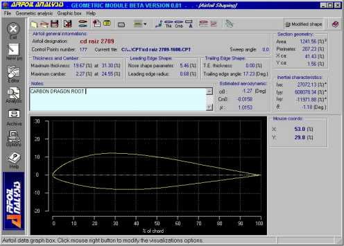
Image 1. Carbon Dragon Wing Root Airfoil
Airfoil Coordinates of the Wing Tip Airfoil
(values on fraction of chord)
|
Coord |
X |
Yu |
Yl |
|
Coord |
X |
Yu |
Yl |
|
0 |
0 |
0 |
0 |
|
31 |
0.363278 |
0.100036 |
-0.0349 |
|
1 |
0.00179 |
0.011632 |
-0.01163 |
|
32 |
0.381174 |
0.098425 |
-0.03364 |
|
2 |
0.005369 |
0.020401 |
-0.01825 |
|
33 |
0.399069 |
0.096994 |
-0.03239 |
|
3 |
0.010737 |
0.027738 |
-0.02523 |
|
34 |
0.416965 |
0.095204 |
-0.03185 |
|
4 |
0.017895 |
0.034896 |
-0.03114 |
|
35 |
0.43486 |
0.093057 |
-0.03042 |
|
5 |
0.025054 |
0.040444 |
-0.0349 |
|
36 |
0.452756 |
0.091267 |
-0.02953 |
|
6 |
0.032212 |
0.046528 |
-0.03758 |
|
37 |
0.470651 |
0.089298 |
-0.02845 |
|
7 |
0.03937 |
0.051897 |
-0.03937 |
|
38 |
0.488547 |
0.086793 |
-0.02756 |
|
8 |
0.048318 |
0.057266 |
-0.04116 |
|
39 |
0.506442 |
0.084109 |
-0.02649 |
|
9 |
0.057266 |
0.063529 |
-0.04295 |
|
40 |
0.524338 |
0.081424 |
-0.02523 |
|
10 |
0.066213 |
0.068003 |
-0.04384 |
|
41 |
0.542233 |
0.07874 |
-0.02416 |
|
11 |
0.075161 |
0.072656 |
-0.04474 |
|
42 |
0.560129 |
0.077666 |
-0.02309 |
|
12 |
0.085898 |
0.076951 |
-0.04545 |
|
43 |
0.578024 |
0.072656 |
-0.02219 |
|
13 |
0.094846 |
0.08053 |
-0.04563 |
|
44 |
0.59592 |
0.069792 |
-0.02112 |
|
14 |
0.103794 |
0.083751 |
-0.04581 |
|
45 |
0.613815 |
0.066571 |
-0.02004 |
|
15 |
0.112742 |
0.086256 |
-0.04563 |
|
46 |
0.631711 |
0.063529 |
-0.01915 |
|
16 |
0.121689 |
0.089298 |
-0.04617 |
|
47 |
0.649606 |
0.060845 |
-0.0179 |
|
17 |
0.130637 |
0.091267 |
-0.04635 |
|
48 |
0.667502 |
0.057266 |
-0.01646 |
|
18 |
0.139585 |
0.093057 |
-0.04653 |
|
49 |
0.685397 |
0.054581 |
-0.01611 |
|
19 |
0.148533 |
0.094846 |
-0.04635 |
|
50 |
0.721188 |
0.048318 |
-0.01432 |
|
20 |
0.166428 |
0.098067 |
-0.04384 |
|
51 |
0.756979 |
0.041696 |
-0.01217 |
|
21 |
0.184324 |
0.100215 |
-0.04295 |
|
52 |
0.79277 |
0.035791 |
-0.01056 |
|
22 |
0.202219 |
0.101467 |
-0.04259 |
|
53 |
0.828561 |
0.029707 |
-0.00823 |
|
23 |
0.220115 |
0.102362 |
-0.0417 |
|
54 |
0.864352 |
0.023264 |
-0.00626 |
|
24 |
0.23801 |
0.103078 |
-0.0408 |
|
55 |
0.900143 |
0.01718 |
-0.00447 |
|
25 |
0.255906 |
0.103615 |
-0.03991 |
|
56 |
0.935934 |
0.010916 |
-0.00268 |
|
26 |
0.273801 |
0.103794 |
-0.03919 |
|
57 |
0.971725 |
0.004295 |
-0.00089 |
|
27 |
0.291696 |
0.103794 |
-0.03812 |
|
58 |
1 |
0 |
0 |
|
28 |
0.309592 |
0.102899 |
-0.0374 |
|
|
|
|
|
|
29 |
0.327487 |
0.102004 |
-0.03669 |
|
|
|
|
|
|
30 |
0.345383 |
0.10111 |
-0.03579 |
|
|
|
|
|
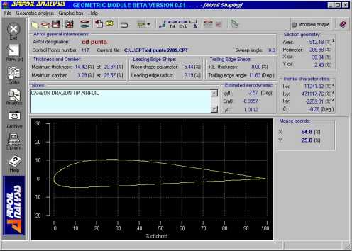
Image 2. Carbon Dragon Wing Tip Airfoil.
Using the software:
The software used was Airfoil Analysis Geometric Module (to get more information and/or demos visit http://airfanalysis.hypermart.net ) developed by two Engineers at Italy.
The data was imported from a text file into the Coorditate Editor to make easier the data imput to the software.
Using both airfoils (root and tip) was possible to get by interpolation the mean geometric chord airfoil, slightly different from the Mean Aerodynamic Chord, for a simply, linearly tapered wing. For this task I used the Airfoil Mix Window and set the mix proportion to 50 %. See the Mean Geometric Chord coordinates table.
With the coordinates of the root, tip and Mean Geometric Chord airfoils the software was able to give the following information:
1 - Geometric data of the airfoils
2 - Estimated aerodynamic data, including:
- Angle of atack for zero lift, a 0
- Pitching moment at zero lift, Cm0
- Lift slope, a0
Airfoil Coordinates of the Wing Mean Geometric Chord Airfoil
(values on fraction of chord)
|
Coord |
x |
Yu |
Yl |
|
0 |
0 |
0 |
0 |
|
1 |
0.0016 |
0.0092 |
-0.0087 |
|
2 |
0.0065 |
0.0184 |
-0.0156 |
|
3 |
0.0145 |
0.028 |
-0.0227 |
|
4 |
0.0257 |
0.0381 |
-0.0286 |
|
5 |
0.04 |
0.05 |
-0.0342 |
|
6 |
0.0573 |
0.0618 |
-0.039 |
|
7 |
0.0774 |
0.0726 |
-0.0431 |
|
8 |
0.1003 |
0.0826 |
-0.0468 |
|
9 |
0.1257 |
0.0915 |
-0.0503 |
|
10 |
0.1536 |
0.0986 |
-0.0531 |
|
11 |
0.1838 |
0.1047 |
-0.0543 |
|
12 |
0.216 |
0.1087 |
-0.0562 |
|
13 |
0.25 |
0.1111 |
-0.0568 |
|
14 |
0.2857 |
0.1119 |
-0.0573 |
|
15 |
0.3227 |
0.1107 |
-0.0572 |
|
16 |
0.3609 |
0.1086 |
-0.0566 |
|
17 |
0.4 |
0.1052 |
-0.0551 |
|
18 |
0.4397 |
0.1006 |
-0.0531 |
|
19 |
0.4799 |
0.0956 |
-0.0507 |
|
20 |
0.5201 |
0.0894 |
-0.0473 |
|
21 |
0.5603 |
0.0837 |
-0.0435 |
|
22 |
0.6 |
0.0757 |
-0.0396 |
|
23 |
0.6391 |
0.0681 |
-0.036 |
|
24 |
0.6773 |
0.0607 |
-0.0318 |
|
25 |
0.7143 |
0.0534 |
-0.0283 |
|
26 |
0.75 |
0.0461 |
-0.0245 |
|
27 |
0.784 |
0.0401 |
-0.0213 |
|
28 |
0.8162 |
0.034 |
-0.0179 |
|
29 |
0.8464 |
0.0282 |
-0.0148 |
|
30 |
0.8743 |
0.0229 |
-0.0113 |
|
31 |
0.8997 |
0.0181 |
-0.0095 |
|
32 |
0.9226 |
0.0138 |
-0.0071 |
|
33 |
0.9427 |
0.0099 |
-0.005 |
|
34 |
0.96 |
0.0066 |
-0.0032 |
|
35 |
0.9743 |
0.0039 |
-0.0018 |
|
36 |
0.9855 |
0.0019 |
-0.0008 |
|
37 |
0.9935 |
0.0007 |
-0.0003 |
|
38 |
0.9984 |
0.0002 |
0 |
|
39 |
1 |
0 |
0 |
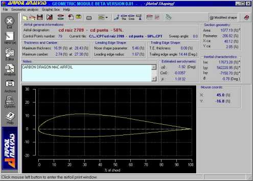
Image 3. Carbon Dragon Mean Geometric Chord.
Geometric Data of the Carbon Dragon Airfoils
|
|
Wing root airfoil |
Mean Geometric Chord airfoil |
Wing tip airfoil |
|
Maximum thickness |
19.67 % |
16.91 % |
14.42 % |
|
Position max. thickness |
31.30 % |
28.43 % |
20.87 % |
|
Maximum camber |
2.27 % |
2.74 % |
3.29 % |
|
Position max. camber |
24.55 % |
27.30 % |
29.57 % |
|
Leading edge radius |
0.68 % |
1.67 % |
2.19 % |
|
Trailing edge angle |
17.23 degrees |
14.44 degrees |
11.63 degrees |
|
Geometric centroid in X |
41.43 % |
40.12 % |
38.34 % |
|
Geometric centroid in Y |
1.56 % |
2.05 % |
2.49 % |
Estimated Aerodynamic Data of the Carbon Dragon Airfoils
|
|
Wing root airfoil |
Mean Geometric Chord airfoil |
Wing tip airfoil |
|
a 0 [degrees] |
-1.27 |
-1.92 |
-2.57 |
|
Cm0 |
-0.0158 |
-0.0357 |
-0.0557 |
|
Lift curve slope efficiency factor m |
1.0153 |
1.0132 |
1.0112 |
|
Lift slope, a0 [1/degree] |
0.111 |
0.111 |
0.110 |
Observations regarding the geometric characteristics of the airfoils:
a) The increasing camber toward the tip should be due to a research of higher maximum lift coefficients to avoid tip stalling.
b) Progressively moving forward the maximum center position should be due to obtain earlier transition on the tip section and minimize Reynolds number effects.
c) The increase of the L.E. radius help to soften tip stall.
For the eager builder/designer:
Some remarks about the “estimated” aerodynamic data presented in AIRFOIL ANALYSIS – GEOMETRIC MODULE: The estimates of zero lift angle and zero lift quarter chord moment coefficient are obtained by the Pankurst’s method (“Theory of Wing Sections”, by Abbott and von Doenhoff) … relying just upon the knowledge of the mean line shape: it’s a sort of Gaussian quadrature and it should had been developed analytically, so no numeric is still present at this stage. The method is surprisingly good, relating to its simplicity, as you own will experience when comparing estimated to calculated data (by the numerical panel method or comparison with experiments). In fact, the flow quality on the airfoil surfaces is still “good” in the proximity of the zero lift angle (that is usually small) for conventional, unflapped airfoils … this explains why these estimates are incredibly useful even if absolutely “a priori” of any aerodynamic analysis as properly defined.
The lift curve slope efficiency factor m (the ratio of the potential flow slope to the theoretical value of 2p) is estimated according to R. Eppler (“Airfoil Design and Data”, Springer Verlag) but it’s usefulness is usually driven off by viscous effects … so practically it doesn’t matter anymore when viscous analysis are on hand.
References:
Airfoil Analysis – Geometric Module
http://airfanalysis.hypermart.net
Engineer Luca Cistriani
http://airfanalysis.hypermart.net
Carbon Dragon Technical Website - by S. Steve Adkins
http://www.isd.net/sadkins/builders.htm
Jim Maupin Ltd.
www.jcpress.com/JMaupinLtd/carbon.htm
The part II of this study will include:
- Presure distibution
- Velocity distribution
- Cl/Cd polars
- Cm/a polars
- Lift slope