|
GRAPHLITE CARBON ROD |
MARSKE AIRCRAFT CORP. 975 Loire Valley Drive Marion, Ohio 43302-6753 phone: (740) 389-3776 FAX: (740 389-2236 Website: www.marskeaircraft.com/workshops.html |
Introducing a new construction material system to build composite aircraft wing spars. Whether your spars are constructed of fiberglass or carbon rovings you must take a serious look at this new miracle structural material. It's more than six times stronger than 2024-T3 aluminum, twice as stiff and nearly half it's weight. Compare this remarkable premanufactured carbon rod with wet layup carbon roving, it's nearly 3-1/2 times stronger in tension and 5-1/2 times as strong in compression.
It's the most exciting material to hit the aerospace market since the introduction of fiberglass. Under the trade name of GRAPHLITE this material is cost effective and consistant in properties. You can build wing spars faster with much greater reliability. Fabricatedt in one operation in a female mold, it cuts assembly time in half. Another benefit of a female mold is that the outside dimensions are always consistant.
The current problem with wet hand laid up carbon roving is that you cannot lay all the filaments down straight or achieve a consistant resin content. As a result your laminate strength has a lot of localized strength deficiencies.
Here is how this problem was solved. A new highly modified pultrusion process, forms a round or rectangular carbon rod in a machine which lays in all filaments straight, parallel and under equal tension. Resin content is closely controlled to +/- one percent. Maximum performance is obtained in every fiber resulting in tensile strengths exceeding 320,000 psi and 275,000 psi compressive strengths, far above the nearest contender. Coupon testing has shown consistant strength values with very small scatter. Modulus of elasticity is 21.5 million.
The GRAPHLITE carbon rods are rolled off a spool, cut to length and laid into a female wing spar mold and embeded in an unfilled epoxy matrix. The rod ends are cut off square with a dremel cut off wheel or a fine tooth hack saw. The rods do not require cleaning nor sanding to improve bond strength. Rather than weaving glass fabric through the rod pack we let the epoxy matrix carry all the shear loads. This is similar to steel reinforcing rod set in concrete for structural beams or roadways.
After working with 'GRAPHLITE' carbon rod for some five years now, I am still impressed with it's incredible strength and light weight. I compared prices of comparable spar cap materials of aluminum, wood andcarbon roving to see what the price difference might be. Would you believe that the carbon rod material is half the cost of all other materials? You see, so little GRAPHLITE is used that the cost is not significant. To give you an example. The new Monarch G, a 42.6 ft span sailplane, uses only four rods (.092 x .220) in each spar cap. Enough rod for one wing panel (upper and lower caps) requires 112 ft. That amounts to 1.44 lbs of rod per wing spar. The total weight of the completed wing spar is 7 lbs which includes blocking for root and strut fittings.
Mat Kollman worked with us on the Monarch project. Mat is a hang glider pilot and recently designed a rigid wing hang glider of 42 ft wingspan and a cantilevered swept back wing called the Raptor. It utilized the same spar and D-tube as the Monarch G. Mat static loaded his cantilevered 'Raptor' wing to a negative 5g without failure. The stress at the root on each spar cap was 155,000 psi at 5g. This is half the stress of what this material is capable of carrying.
Because the Monarch uses a wing strut the bending stresses on the wing are not as great as the Raptor's. The strut intersects the wing 5.5 ft out from the fuselage. Calculating the rod stress at the strut junction at 155,000 psi comes to 10.2g. Despite all this extra strength the spar cap weight in either of these craft weighs less than 1.5 lbs per wing panel. Samples of the rod have been tested at a laboratory to 326,000 to 333,000 psi in tension. Compression failure excedes 275,000 psi. Lab tests on hand laid up carbon rovings failed in the range of 47,000 psi to 80,000 psi in compression. A shocking realization.
The Genesis was the first sailplane to use the 'GRAPHLITE' carbon rod. The Genesis is a 15 meter (49.2 ft) production sailplane with a slightly swept forward wing. During static testing a completed wing the test holding fixture failed at 19g. Test conditions were: a 260 lb pilot and 50 lbs of equipment. Extensive dynamic cyclic testing was also performed. 20,000 cycles in positive and negative loading, many above the design limit, failed to show any visual sign of rod failure or separation from the binding matrix.
The prototype Genesis sailplane had a hand lay up spar from contineous carbon roving. The spar weight was 38 lbs. The production Genesis with the GRAPHLITE rod spar weighed only 25 lbs but was twice as strong. A third generation spar of GRAPHLITE for the Genesis would weigh under 20 lbs and be of equal strength. Just for the record, an equivilent aluminum spar would would weigh 65 lbs and be half as strong.
The Lithuanian engineers were so impressed witnessing the Genesis static and dynamic test that their new sailplane, the 18 meter (59 ft span) LAK-17A, incorporates these rods in the mainspar also. What impresses me is the spar depth at the root of the LAK-17A is only 3.5 inches. Aspect ratio is 33 to 1. And the wing panel weight is only 122 lbs.!!
The spar, such as used on the Monarch G and Raptor, is easy to make - even for a one-off aircraft. Bend up a piece of metal sheet with 1.5" high flanges top and bottom. Use this channel as your mold. Wax and PVA the mold. Lay in the channel one layer of 9 oz bid cloth, with weave at 45 degrees, and brush into it a coat of epoxy. Next place a carbon rod, full length, into each corner and laying flat. Wet out the rod well with epoxy resin. Lay the second rod on top of the first and wet out. This rod is shorter. Lay in the third rod which is shorter still. Add a fourth and perhaps a fifth depending on strength requirements. Now lay in a layer of 8.6 oz bid glass cloth into the channel and up the flanges packing the cloth tightly around the two stacks of carbon rods. It is recommended that the rod pack always be completely wrapped in glass cloth to prevent delamination from the shear web.
If you wish, two channels may be bonded back to back to form an 'I' beam for heavy duty spars. A 6mm PVC foam sheet can be bonded between these two channel spars to act as a vertical stiffner.
The stickler here is deflection. Because so little carbon rod is required and the material is so strong the beam just keeps bending as the load is increased. Don't let the high modulus fool you, the modulus of elasticity of GRAPHLITE (21 mil) is twice that of aluminum (10 mil ). We can illustrate the deflection if you look at the material stretch in tension at yield strength. Aluminum (6061-T6) has a modulus of 10 mil and a yield strength of 35,000 psi. Divide the modulus into the yield strength and you have (35,000 / 10,000,000 ) .0035" material stretch per inch of length at yield. For GRAPHLITE it's (320,000 / 21,000,000 = ) .015". Thats ( .015 / .0035 = ) 4.29 times more deflection for GRAPHLITE over aluminum. For sitka spruce it's: (9,500 / 1,300,000 = ) .00731". Here GRAPHLITE is 2.05 times as flexible in tension. For unidirectional fiberglass rovings it's (80,000 / 5,000,000 = ) .016". And thats nearly the same as GRAPHLITE. The difference here is; You are using 4 times less material (in carbon) plus carbon is 20% lighter per cubic inch than fiberglass. So you have, by comparison, for the same strength and deflection, a cap weight of 20 lbs in glass but only 4.2 lbs in GRAPHLITE.
If you are building a short thick wing the deflection is probably not a problem. However, sailplane wings are long and thin. By doubling the number of rods in the cap the deflection is cut in half. You can do this by degrading the rod strength in half to 160,000 psi. However, you are still way ahead in weight and cost savings.
Some builders want to mix the rod into a wood spar. Yes, you can do this. It's not as weight efficient as an all carbon spar but the little weight added is far offset by the strength gained. How much rod needs to be added? Lets say you have an I-beam spar with an upper cap cross sectional area of 1 square inch it would take .05 square inch of GRAPHLITE, or 4 rods of .125" dia, to double the strength of the spar.
You need not scuff the surface of the rod prior to bonding. In fact, no surface preparation is required. Most pultruded rod has oil added to the resin to assure smooth flow through the dies. The GRAPHLITE manufacturing process does not require any foreign matter to be mixed into the die during the cure cycle. The matrix, or binder, of the carbon fibers is, Bis F Epoxy. Remember, epoxy likes to bond itself to epoxy.
GRAPHLITE carbon rod is stronger than all other carbon because all fibers run in the same direction, are perfectly straight, and are under equal tension. Since it is machine made the resin content is closely controlled and laboratory tested breaking strength is repeatable with very small variation.
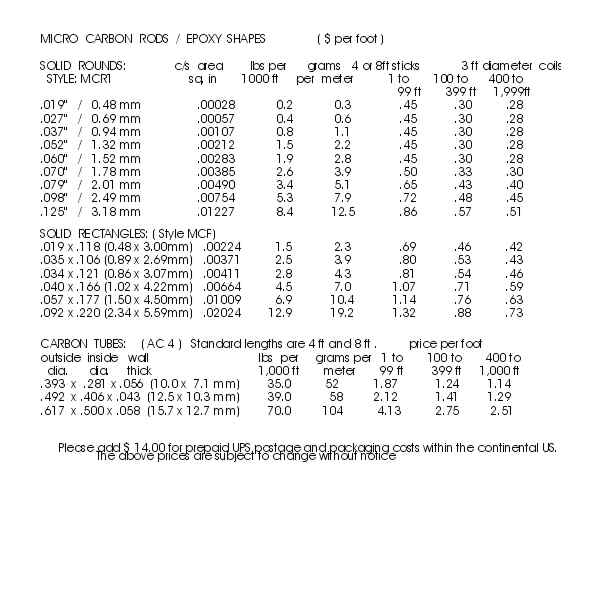
The GRAPHLITE carbon rod comes in many sizes but the two recommended sizes are .125" (3.16mm) diameter and .092 x .220" (2.34 x 5.59mm) rectangular rod. Cost of the GRAPHLITE rod varies and depends on the quantity purchased. Small quantities, under 100 ft, may run $1.00 per foot and quantities of 500 ft, is $.65 per ft.
Where do you get this wonder material? There is only one factory in the US that makes GRAPHLITE using this special process. It's inventor, Reggie Durhman, says it's a highly modified pulltrusion process. So if you want to try this great stuff get in touch with me at: Marske Aircraft Corp., 975 Loire Valley Drive, Marion, Ohio 43302. Phone: (740)389-3776, FAX (740)389-2236.
| TYPICAL MATERIALS USED IN AIRCRAFT CONSTRUCTION |
|
|
This is the spar as fabricated for a Monarch G wing. It is quick and simple to build. A nice feature of this mold is that it is used for both wings, no need to make a second spar mold. The is laid up in a channel mold which has been waxed and PVA'd. The rods are stacked parallel to the flange. They could be stacked parallel to the web if so desired. There is no vertical stiffener for the web. No nose ribs are placed at 9" spacing with it's flange bonded against the web which has proven to be adequate under static load. We have found that one man can fabricate a spar in less than 4 hours. A woman can do it in less time. It's true.
The question always comes up as how to attach root end fittings. You cannot (must not) drill holes through the carbon rods. The cap loads are transfered into a fiberglass plate and then into the metal fittings. Note that glass laminates transfer the load from the cap to the plate. It is important that the carbon caps and glass plate are encapsulated in glass fabric. The exact size of the plate, metal fittings and bolts depend on the stresses involved.
Spars are molded in female molds as a channel shape with flanges facing downwards. An I-beam is produced by bonding two channels back to back.
|
|
| MARSKE AIRCRAFT CORP. 975 Loire Valley Drive Marion, Ohio 43302-6753 |
phone: (740) 389-3776 FAX: (740) 389-2236 Website: www.marskeaircraft.com/workshops.html |