Technical Plans for the Carbon Dragon
The Carbon Dragon is an ultralight, high performance glider conceived by the late Jim Maupin who also designed the famous Woodstock sailplane and the Windrose motorglider. Jim received encouragement from Irv Culver, who promised to "run the numbers". As a result, Jim Maupin with an assist from co-designer Irv Culver, produced an exciting sailplane for which at least 476 plan sets have been sold. The detailed plans were drawn by Bill Baker whom Maupin described as, "... a fellow home builder and consummate draftsman." Many people, who have flown the prototype, have commented on its excellent handling.
Plans for the Carbon Dragon are no longer available for purchase, though it is sometimes possible (if you're very lucky) to pick these up on eBay. Jim Maupin expressed hope that designers would take this design to the next level. Modern composite materials, especially carbon, now make this dream possible. A scanned set of plans has been available on the internet for some years and is reproduced here for archival purposes:
Full Scale Plans
Full Scale Plans
(Click here to download the full scale plans - 27.2Mb)
NOTE: Although these are 'full-scale' plans, the actual scale of the plans when printed out varies by +/- a percent or so from drawing to drawing. It is very important to check the *actual* scale of each drawing and mark this on each sheet. You will need to use extreme caution when working from these drawings to ensure that you build each part to the correct dimensions - Do NOT trust the scale of these drawings! That said... these are the drawings I am working from. I got them printed out through my brother's engineering company which regularly prints out large drawings. The drawings are roughly 4' x 2' each in size.
To work out the actual scale of each drawing find the largest indicated dimension on the drawing (the larger the part you are measuring, the smaller your error will be):
Actual Scale = Physical Measurement of the Drawing / Dimension Indicated on the Drawing x 100
So, if you measure a part on the drawing using a ruler at 15.1" and the drawing states that the full scale dimension is 60" then the Actual Scale of the drawing is 15.1 / 60 x 100 = 25.17%
Scale Factor = Dimension Indicated on the Drawing / Physical Measurement of the Drawing
Using the same measurement and dimension off the drawing, the Scale Factor = 60 / 15.1 = 3.97x
Check the Actual Scale and Scale Factor in both the X and Y dimensions on every drawing and apply the Scale Factor to all measurments you take off the drawings for every part.
8mm Ply
Throughout the drawings you will see reference to '8mm ply'. This should read '0.8mm or 1/32" Ply'.
This very thin plywood is used for all the leading edges, spar webs and rib gussets.
Rudder
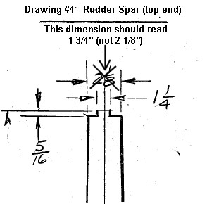
One of the dimensions of the rudder spar on drawing #4 is incorrect.
Drawing #4 shows the width of the top end of the spar to be 2 1/8", which is too wide.
It should read 1 3/4".
All the other dimensions on the drawing are correct.
SOLUTION: Make the rudder spar with a top end width of 1 3/4" rather than 2 1/8". Everything then fits!
I discovered this error while assembling my rudder (gluing the hinges, hinge supports, D-section formers, etc.) to the rudder spar. The triangular ribs are are not the same width as the spar where they are supposed to be bonded to it.
I double checked my spar and its physical dimensions are exactly as specified in the plans. The ribs were made using the plans as a template and my ribs match the plans with better than 1mm accuracy but I was at a loss as to why there is a growing disparity in the with of the ribs as you go up the spar:
Rib# Spar Width Rib Width Difference
6 54mm 44.5mm 9.5mm
5 63mm 58mm 5mm
4 72mm 69mm 3mm
3 82mm 79mm 3mm
2 92mm 91mm 1mm
1 102mm 103mm 1mm
Rib #6 was particularly bad - the spar is 54mm (2 1/8") wide at the top but the width of the rib where it joins the spar is 44.5mm (1 3/4") - there's no way this was a scaling error on my printed plans! I checked the scale of my drawings and it was close enough to the correct scale that this did not account for the error. What was I missing???
I emailed Rick Mullins who responded immediatly with the (now!) obvious answer:
Rick replied: "Yeah, you've discovered one of the many errors in the plans. The drawings show the overall width [at the top of the rudder spar] as 2 1/8" and the space between the rib stringers as being 1 1/4". However the rib stringers are made of 1/4" spruce and 1 1/4" + 1/4" + 1/4" = 1 3/4. I made notes in my plans when I found errors but missed marking this one."
Control Stick Assembly
Following on from the error on drawing #4 of the rudder spar top end, Rick Mullins highlights a few more errors he found the hard way:
Yeah there were a few parts I remade because I didn't catch the errors soon enough.
When you get to the control stick and pivot assembly on sheet 20 you'll see he must have been having a bad day. I made those pieces and welded them wrong 2 times before I caught it.
The left drawing of the pivot plate shows the head of the bolt and the flat side to the left. All the other drawings show the shaft side of the pivot plate with the flat side still on the left.
If you are looking at the pivot plate on the bolt head side, the flat side should be to the right, the left drawing is wrong.
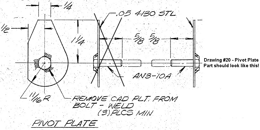
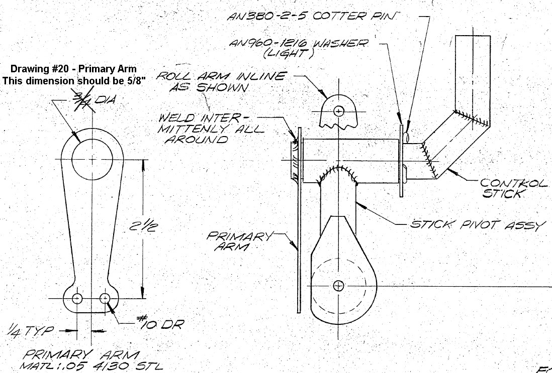
Also the control stick is made of 5/8" steel so the hole in the primary arm should be 5/8", not 3/4" as shown in the plans.
H-Stab & Elevator Hinges
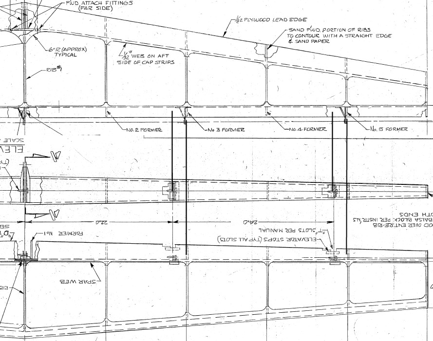
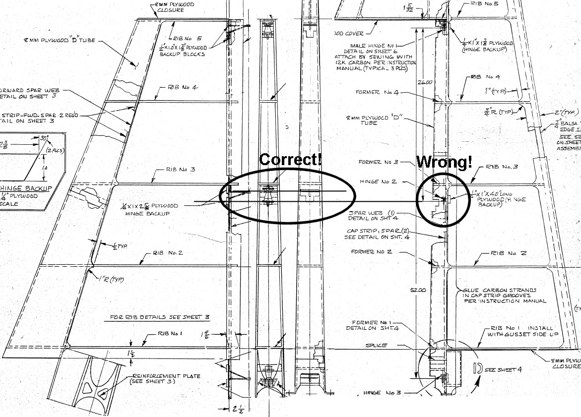
The other big error that Rick Mullins encountered during his build is to be found on drawings #5 and #6 of the Horozontal Stabiliser and Elevator. On the drawing of the Horozontal Stabiliser the hinges are mounted aligned with the ribs and D-section formers, but are shown significantly offset on the drawing of the Elevator - they don't line up! You will need to make sure that you mount the male side of the hinges (the side with the tapered pins) are correctly aligned to mate with their female counterparts. You will also need to make the appropriate cut-outs in the bases of the D-section formers to allow the base / flange of the male hinge to be bonded under the formers. The formers can be bonded into the centre slot of the male hinge with the tapered pin passing through the D-former.
Rudder Hinges
The two halves of the middle rudder hinge do not lign up on drawing #2. The male half of the hinge is shown incorrectly positioned on the drawing of the rudder but shown correctly in the drawing of the rudder spar just next to it. This is easily caught as the male halves are bonded to the rudder spar with the hinge pins inserted into the female halves already bonded to the tail fin rear spar to ensure perfect alignment.
Tail Fin Front Spar
Drawing #3 shows an incorrect dimension for the lower end of the vertical tail fin front spar web. The half-width of the spar web is correctly shown as 2.41" but the full width is incorrectly shown as 2.82". It should read 4.82".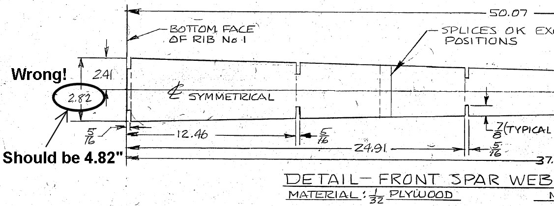
Note also that the spar caps extend beyond the bottom of the spar web. The spar web is 50.07" long but the spar caps need to be 58 13/16" (58.8125") to reach down the sides of the tail boom as they taper off. This is important to note if you are laying up this spar using composites and carbon rod for the spar caps - don't leave yourself short (like I did!) Also, the reinforcement plate at the bottom of this spar can be incorporated into the spar during lay-up. I pre-fabricated my reinforcement plate out of 5mm foam board with seven layers of carbon cloth either side.
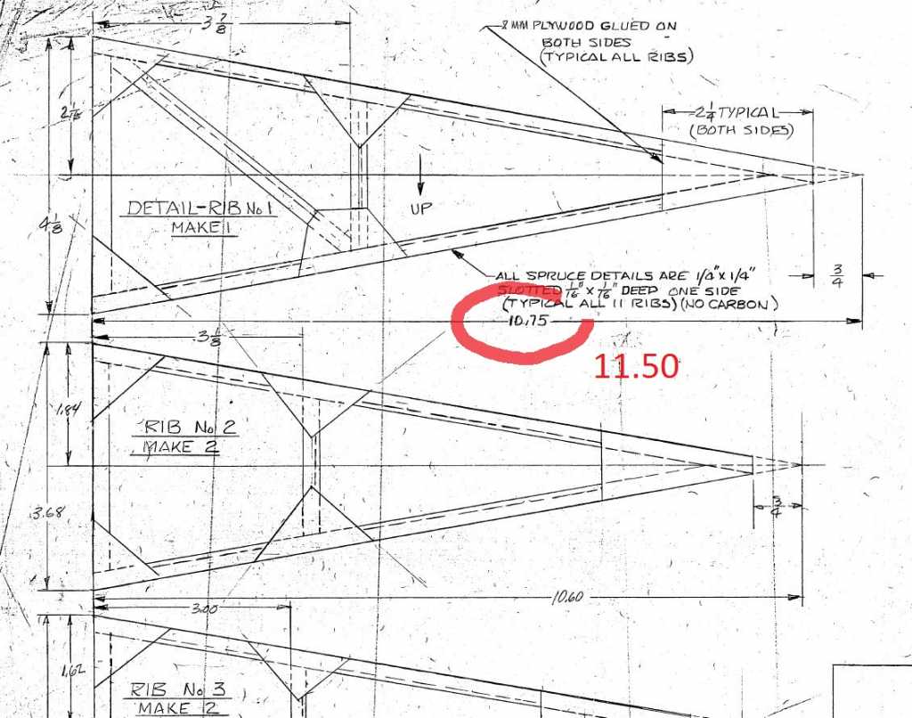
Elevator Rib 1
Thanks to Bertrand Botrel for spotting this one!
The dimension shown of Rib #1 on Drawing #6 is incorrect. It should read 11.5" (not 10.75")
Thankfully the drawing itself is correct and may be used as a template.
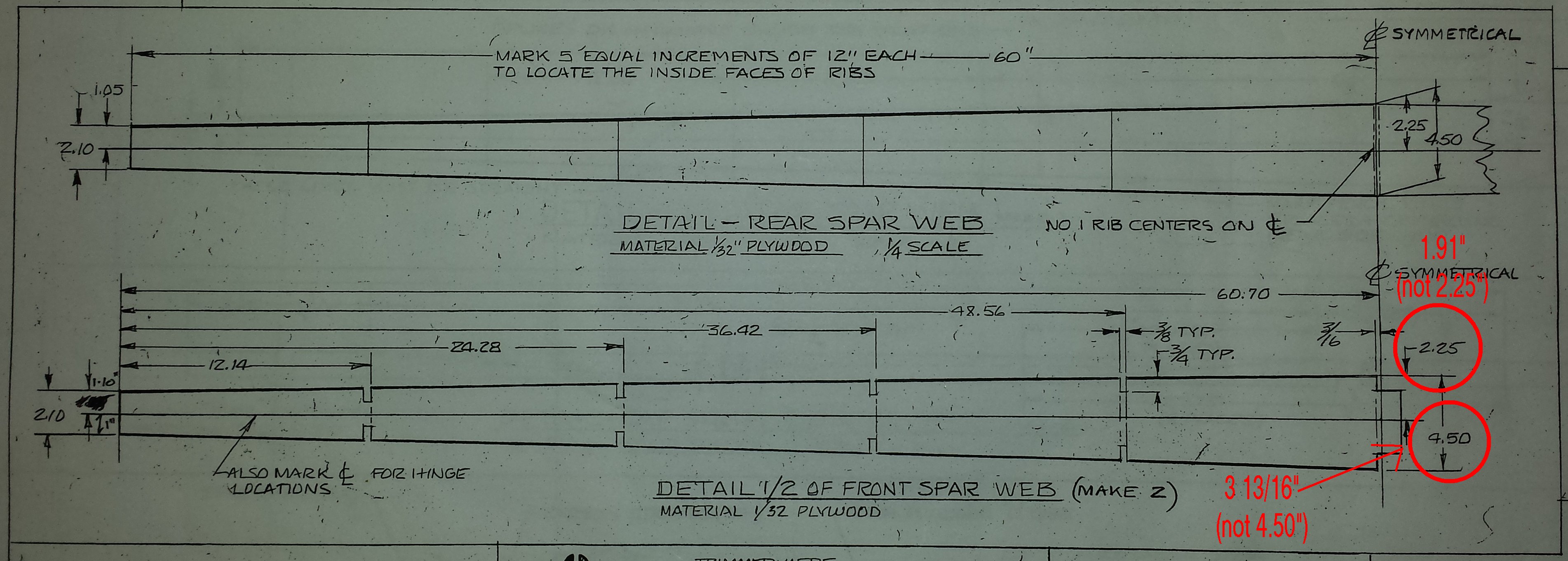
Horizontal Stabiliser Front Spar
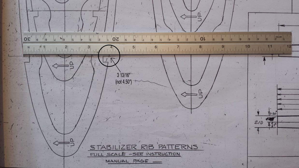
Drawing #5 shows two incorrect dimensions for the widest point on the front spar of the horizontal stabiliser. The drawing of the front spar gives the widest point (at Rib #1) as 4.50", which does not match the dimension of Rib #1 where it is bonded to the spar. Direct measurement of Rib #1 (which is drawn full scale on Drawing #5) reveals that the correct dimension of the spar at this point should be 3 13/16ths". The half-width dimension is also incorrect and should read 1.91" rather than 2.25".
Elevator Cable Pulley Brackets
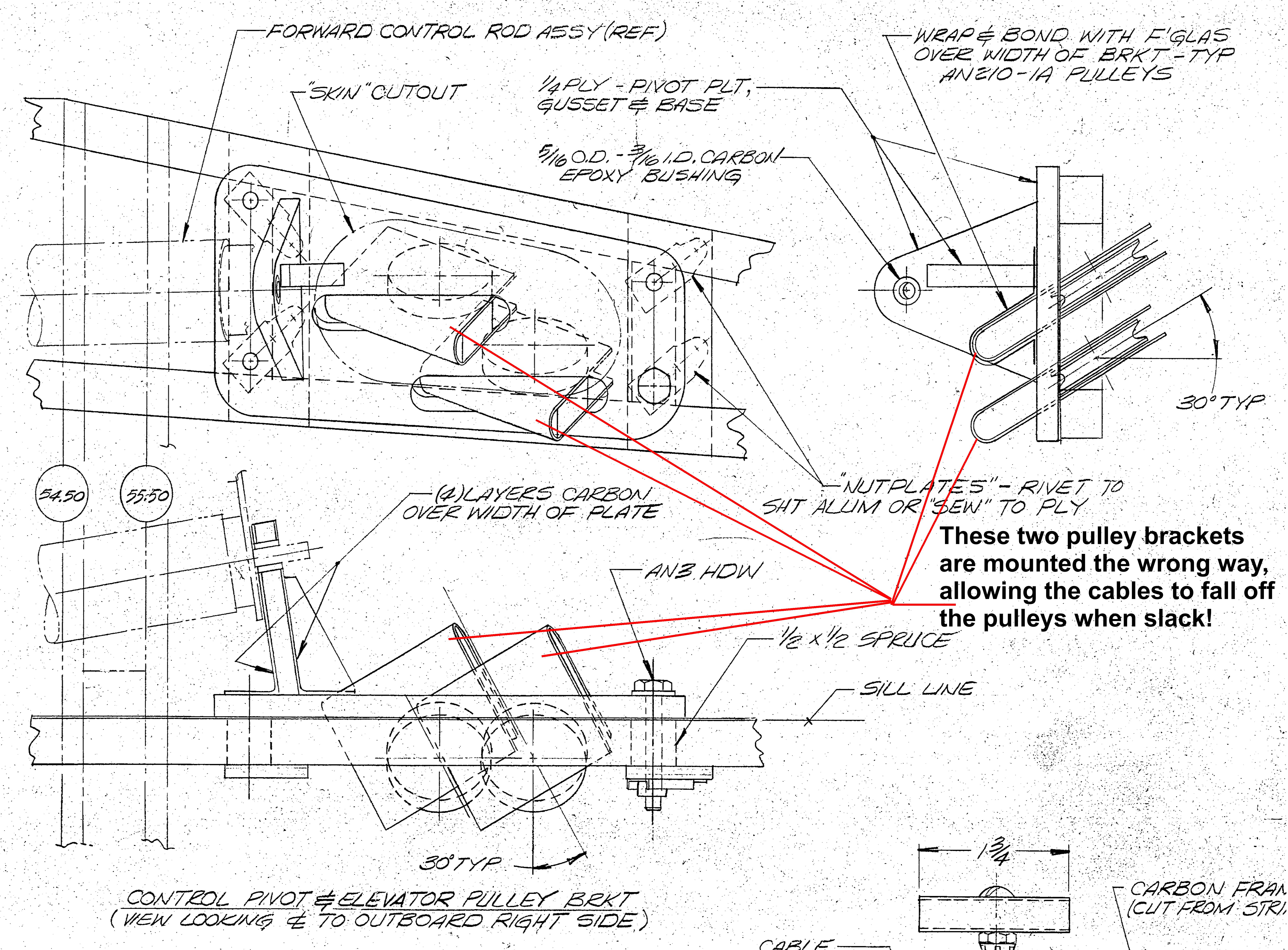
I should have spotted this much earlier, but on Drawing #21, the two Elevator Pulley Brackets are shown mounted upside down. Made to the plans (as I did!) the two elevator cables are able to fall off the pulleys when the cables are slack or loose. This is not a problem as long as the cables are kept under tension, but they must be double checked if you detach the cables for any reason.
The carbon brackets that envelope the pulleys should be mounted the other way up, in such a way as to prevent this problem.
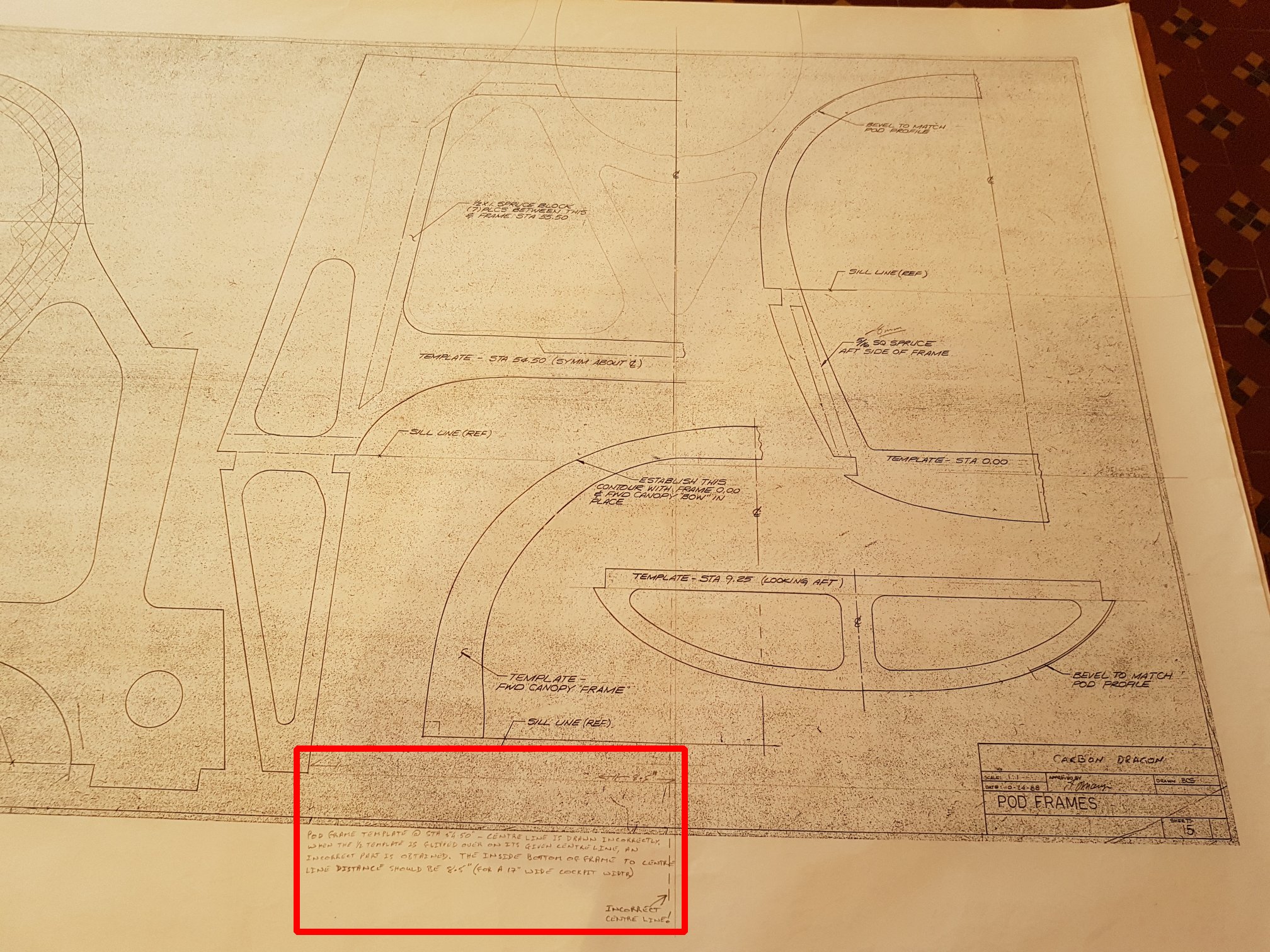
Pilot Pod Template 54.50"
Pod Frame Template at 54.50" - the centre line is drawn incorrectly. When the 1/2 template is flipped over on its given centre line, an incorrect part is obtained. The inside bottom of frame-to-centre-line distance should be 8.5" for a 17" wide cockpit width.
Builder's Manual
Builder's Manual (Original & Electronic)
(Click here to download an archive of both versions of the Builder's Manual)
The original Builder's Manual is included (along with an electronic MS-Word document version) because, in places, the plans refer to specific pages in the original Builder's Manual. The Word document version, while more useful and searchable, has lost the pagination of the original, making the references on the drawings difficult to follow.
Phil's Wing Stress Analysis
Analysing the Loads and Stresses Along the Wing
My wing calculations are based on the formulae and method described in Jim Marske's Composite Design Manual. If you don't yet have a copy of this manual then I strongly recommend that you buy a copy, even if you don't intend to do the calculations yourself for your own design loads - it contains a large amount of practical knowledge about working with and fabricating composites. The photos, below, are of my initial hand written calculations, refrencing the appropriate pages in Jim Marske's manual, and show the formula and description of the method used to arrive at the numbers in my spreadsheet.

Download my spreadsheet here - it summarises all the calculations below and allows you to enter your own initial design loads to see what effect they have on the various parts of the wing.
I designed my Carbon Dragon to my own specific load criteria. I take absolutely no responsibility or accept any liability whatsoever for any adverse consequences should you build your own Carbon Dragon to the same design configuration as detailed in my calculations or for using my spreadsheet and any design numbers that you may obtain from it by modfying the initial circumstances. You use my calculations and spreadsheet entirely at your own risk.
Click here to download an archive of Phil Lardner's wing load/stress analysis
Aerodynamic Analysis
AERODYNAMIC ANALYSIS OF THE CARBON DRAGON AIRFOILS
PART ONE
About the author:
Alejandro Ramirez-Pineiro (30) has the degree of Bachelor of Science in Mechanical Engineering, earned at the Universidad Tecnologica Metropolitana of Santiago, Chile. At this moments he is working as a Composite Materials Engineer at ENAER, building a 100% composite JAR 23 airplane (visit www.euro-enaer.com ). Also he is building a modified Carbon Dragon, planned to fly during the first quarter of 2000. You can reach him at This email address is being protected from spambots. You need JavaScript enabled to view it.">This email address is being protected from spambots. You need JavaScript enabled to view it. .
Introduction:
The Carbon Dragon is an ultralight, high performance glider. This glider was conceived by Jim Maupin who also designed the famous Woodstock sailplane and the Windrose motorglider. With encouragement from Irv Culver, who promised to "run the numbers", Jim Maupin finished the design and built the prototype. As a result, Jim Maupin with an assist from co-designer Irv Culver, produced an exciting sailplane.
Scope of the study:
The proposal of this study is getting aerodynamic data that can be used for the structural modifications of the original Carbon Dragon. This data will be used also on the study of the longitudinal static stability of the modified glider. All the aerodynamic values presented here can be useful to actual or future builders for helping their own studies.
For preliminary design, the values presented in this report are excelent, but must to keep in mind that the data presented here was developed by a computer software, so, to get more “real” values, the reader will have to do wind tunnel testing.
Getting the coordinates:
To get the coordinates of the wing root and wing tip airfoils, the original drawings of the ribs number 1 and number 13 where divided on 88 stations on the root and 58 stations on the tip. The mesures where taken with an accuracy of + - 0.5 mm. The job was done by my building partner Miguel Eyquem.
With the coordinates obtained in milimiters, the next step was to convert them in fractions of chord. For this task I used an electronic spreadsheet.
Airfoil Coordinates of the Wing Root Airfoil
(values on fraction of chord)
|
Coord
|
x
|
Yu
|
Yl
|
|
Coord
|
X
|
Yu
|
Yl
|
|
0
|
0
|
0
|
0
|
|
51
|
0.361367
|
0.116951
|
-0.07819
|
|
1
|
0.001314
|
0.00657
|
-0.00591
|
|
52
|
0.374507
|
0.115966
|
-0.07819
|
|
2
|
0.003285
|
0.010184
|
-0.00828
|
|
53
|
0.387648
|
0.114652
|
-0.07806
|
|
3
|
0.00657
|
0.014783
|
-0.0115
|
|
54
|
0.400788
|
0.113338
|
-0.07779
|
|
4
|
0.009855
|
0.018725
|
-0.0138
|
|
55
|
0.413929
|
0.111695
|
-0.0772
|
|
5
|
0.013141
|
0.022339
|
-0.01577
|
|
56
|
0.42707
|
0.110381
|
-0.07668
|
|
6
|
0.016426
|
0.026281
|
-0.01774
|
|
57
|
0.44021
|
0.108541
|
-0.07615
|
|
7
|
0.019711
|
0.029566
|
-0.01971
|
|
58
|
0.453351
|
0.106767
|
-0.0753
|
|
8
|
0.022996
|
0.032852
|
-0.02102
|
|
59
|
0.466491
|
0.105125
|
-0.07424
|
|
9
|
0.026281
|
0.035808
|
-0.02234
|
|
60
|
0.479632
|
0.103154
|
-0.07326
|
|
10
|
0.029566
|
0.038765
|
-0.02431
|
|
61
|
0.492773
|
0.101183
|
-0.07194
|
|
11
|
0.032852
|
0.041393
|
-0.02562
|
|
62
|
0.505913
|
0.099212
|
-0.0707
|
|
12
|
0.036137
|
0.044678
|
-0.02727
|
|
63
|
0.519054
|
0.096912
|
-0.06932
|
|
13
|
0.039422
|
0.047306
|
-0.02858
|
|
64
|
0.532194
|
0.094941
|
-0.06754
|
|
14
|
0.042707
|
0.049934
|
-0.02989
|
|
65
|
0.545335
|
0.092576
|
-0.06597
|
|
15
|
0.045992
|
0.052562
|
-0.03121
|
|
66
|
0.565046
|
0.08883
|
-0.06334
|
|
16
|
0.049277
|
0.054534
|
-0.03252
|
|
67
|
0.584757
|
0.085414
|
-0.06064
|
|
17
|
0.052562
|
0.056505
|
-0.03351
|
|
68
|
0.604468
|
0.08134
|
-0.05782
|
|
18
|
0.055848
|
0.059133
|
-0.03463
|
|
69
|
0.624179
|
0.076938
|
-0.05519
|
|
19
|
0.059133
|
0.061104
|
-0.03581
|
|
70
|
0.64389
|
0.07293
|
-0.05256
|
|
20
|
0.062418
|
0.063403
|
-0.03679
|
|
71
|
0.663601
|
0.06866
|
-0.04961
|
|
21
|
0.065703
|
0.065703
|
-0.03784
|
|
72
|
0.683311
|
0.064389
|
-0.04652
|
|
22
|
0.072273
|
0.068988
|
-0.04008
|
|
73
|
0.703022
|
0.05979
|
-0.04336
|
|
23
|
0.078844
|
0.072273
|
-0.04172
|
|
74
|
0.722733
|
0.055191
|
-0.04074
|
|
24
|
0.085414
|
0.075558
|
-0.04382
|
|
75
|
0.742444
|
0.050591
|
-0.03752
|
|
25
|
0.091984
|
0.078844
|
-0.04534
|
|
76
|
0.762155
|
0.047306
|
-0.03476
|
|
26
|
0.098555
|
0.0818
|
-0.04731
|
|
77
|
0.781866
|
0.043364
|
-0.03187
|
|
27
|
0.105125
|
0.084757
|
-0.04901
|
|
78
|
0.801577
|
0.039093
|
-0.02891
|
|
28
|
0.111695
|
0.087385
|
-0.05099
|
|
79
|
0.821288
|
0.035085
|
-0.02602
|
|
29
|
0.118265
|
0.090013
|
-0.05256
|
|
80
|
0.840999
|
0.031012
|
-0.023
|
|
30
|
0.124836
|
0.092313
|
-0.05414
|
|
81
|
0.86071
|
0.026938
|
-0.0203
|
|
31
|
0.131406
|
0.094415
|
-0.05565
|
|
82
|
0.88042
|
0.022996
|
-0.01537
|
|
32
|
0.137976
|
0.096583
|
-0.05696
|
|
83
|
0.900131
|
0.018922
|
-0.01445
|
|
33
|
0.144547
|
0.098555
|
-0.05848
|
|
84
|
0.919842
|
0.01498
|
-0.0113
|
|
34
|
0.151117
|
0.100657
|
-0.05999
|
|
85
|
0.939553
|
0.010841
|
-0.00821
|
|
35
|
0.157687
|
0.102497
|
-0.0611
|
|
86
|
0.959264
|
0.006899
|
-0.00512
|
|
36
|
0.164258
|
0.104205
|
-0.06242
|
|
87
|
0.978975
|
0.002957
|
-0.0021
|
|
37
|
0.177398
|
0.107753
|
-0.06472
|
|
88
|
1
|
0
|
0
|
|
38
|
0.190539
|
0.11071
|
-0.06669
|
|
|
|
|
|
|
39
|
0.203679
|
0.113009
|
-0.06866
|
|
|
|
|
|
|
40
|
0.21682
|
0.115375
|
-0.07063
|
|
|
|
|
|
|
41
|
0.229961
|
0.116754
|
-0.07194
|
|
|
|
|
|
|
42
|
0.243101
|
0.118265
|
-0.07293
|
|
|
|
|
|
|
43
|
0.256242
|
0.119054
|
-0.07392
|
|
|
|
|
|
|
44
|
0.269382
|
0.119842
|
-0.0749
|
|
|
|
|
|
|
45
|
0.282523
|
0.119908
|
-0.07589
|
|
|
|
|
|
|
46
|
0.295664
|
0.11958
|
-0.07654
|
|
|
|
|
|
|
47
|
0.308804
|
0.119251
|
-0.07727
|
|
|
|
|
|
|
48
|
0.321945
|
0.119054
|
-0.07753
|
|
|
|
|
|
|
49
|
0.335085
|
0.118594
|
-0.07786
|
|
|
|
|
|
|
50
|
0.348226
|
0.117937
|
-0.07819
|
|
|
|
|
|
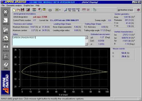
Image 1. Carbon Dragon Wing Root Airfoil
Airfoil Coordinates of the Wing Tip Airfoil
(values on fraction of chord)
|
Coord
|
X
|
Yu
|
Yl
|
|
Coord
|
X
|
Yu
|
Yl
|
|
0
|
0
|
0
|
0
|
|
31
|
0.363278
|
0.100036
|
-0.0349
|
|
1
|
0.00179
|
0.011632
|
-0.01163
|
|
32
|
0.381174
|
0.098425
|
-0.03364
|
|
2
|
0.005369
|
0.020401
|
-0.01825
|
|
33
|
0.399069
|
0.096994
|
-0.03239
|
|
3
|
0.010737
|
0.027738
|
-0.02523
|
|
34
|
0.416965
|
0.095204
|
-0.03185
|
|
4
|
0.017895
|
0.034896
|
-0.03114
|
|
35
|
0.43486
|
0.093057
|
-0.03042
|
|
5
|
0.025054
|
0.040444
|
-0.0349
|
|
36
|
0.452756
|
0.091267
|
-0.02953
|
|
6
|
0.032212
|
0.046528
|
-0.03758
|
|
37
|
0.470651
|
0.089298
|
-0.02845
|
|
7
|
0.03937
|
0.051897
|
-0.03937
|
|
38
|
0.488547
|
0.086793
|
-0.02756
|
|
8
|
0.048318
|
0.057266
|
-0.04116
|
|
39
|
0.506442
|
0.084109
|
-0.02649
|
|
9
|
0.057266
|
0.063529
|
-0.04295
|
|
40
|
0.524338
|
0.081424
|
-0.02523
|
|
10
|
0.066213
|
0.068003
|
-0.04384
|
|
41
|
0.542233
|
0.07874
|
-0.02416
|
|
11
|
0.075161
|
0.072656
|
-0.04474
|
|
42
|
0.560129
|
0.077666
|
-0.02309
|
|
12
|
0.085898
|
0.076951
|
-0.04545
|
|
43
|
0.578024
|
0.072656
|
-0.02219
|
|
13
|
0.094846
|
0.08053
|
-0.04563
|
|
44
|
0.59592
|
0.069792
|
-0.02112
|
|
14
|
0.103794
|
0.083751
|
-0.04581
|
|
45
|
0.613815
|
0.066571
|
-0.02004
|
|
15
|
0.112742
|
0.086256
|
-0.04563
|
|
46
|
0.631711
|
0.063529
|
-0.01915
|
|
16
|
0.121689
|
0.089298
|
-0.04617
|
|
47
|
0.649606
|
0.060845
|
-0.0179
|
|
17
|
0.130637
|
0.091267
|
-0.04635
|
|
48
|
0.667502
|
0.057266
|
-0.01646
|
|
18
|
0.139585
|
0.093057
|
-0.04653
|
|
49
|
0.685397
|
0.054581
|
-0.01611
|
|
19
|
0.148533
|
0.094846
|
-0.04635
|
|
50
|
0.721188
|
0.048318
|
-0.01432
|
|
20
|
0.166428
|
0.098067
|
-0.04384
|
|
51
|
0.756979
|
0.041696
|
-0.01217
|
|
21
|
0.184324
|
0.100215
|
-0.04295
|
|
52
|
0.79277
|
0.035791
|
-0.01056
|
|
22
|
0.202219
|
0.101467
|
-0.04259
|
|
53
|
0.828561
|
0.029707
|
-0.00823
|
|
23
|
0.220115
|
0.102362
|
-0.0417
|
|
54
|
0.864352
|
0.023264
|
-0.00626
|
|
24
|
0.23801
|
0.103078
|
-0.0408
|
|
55
|
0.900143
|
0.01718
|
-0.00447
|
|
25
|
0.255906
|
0.103615
|
-0.03991
|
|
56
|
0.935934
|
0.010916
|
-0.00268
|
|
26
|
0.273801
|
0.103794
|
-0.03919
|
|
57
|
0.971725
|
0.004295
|
-0.00089
|
|
27
|
0.291696
|
0.103794
|
-0.03812
|
|
58
|
1
|
0
|
0
|
|
28
|
0.309592
|
0.102899
|
-0.0374
|
|
|
|
|
|
|
29
|
0.327487
|
0.102004
|
-0.03669
|
|
|
|
|
|
|
30
|
0.345383
|
0.10111
|
-0.03579
|
|
|
|
|
|
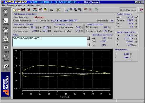
Image 2. Carbon Dragon Wing Tip Airfoil.
Using the software:
The software used was Airfoil Analysis Geometric Module (to get more information and/or demos visit http://airfanalysis.hypermart.net ) developed by two Engineers at Italy.
The data was imported from a text file into the Coorditate Editor to make easier the data imput to the software.
Using both airfoils (root and tip) was possible to get by interpolation the mean geometric chord airfoil, slightly different from the Mean Aerodynamic Chord, for a simply, linearly tapered wing. For this task I used the Airfoil Mix Window and set the mix proportion to 50 %. See the Mean Geometric Chord coordinates table.
With the coordinates of the root, tip and Mean Geometric Chord airfoils the software was able to give the following information:
1 - Geometric data of the airfoils
2 - Estimated aerodynamic data, including:
- Angle of atack for zero lift, a 0
- Pitching moment at zero lift, Cm0
- Lift slope, a0
Airfoil Coordinates of the Wing Mean Geometric Chord Airfoil
(values on fraction of chord)
|
Coord
|
x
|
Yu
|
Yl
|
|
0
|
0
|
0
|
0
|
|
1
|
0.0016
|
0.0092
|
-0.0087
|
|
2
|
0.0065
|
0.0184
|
-0.0156
|
|
3
|
0.0145
|
0.028
|
-0.0227
|
|
4
|
0.0257
|
0.0381
|
-0.0286
|
|
5
|
0.04
|
0.05
|
-0.0342
|
|
6
|
0.0573
|
0.0618
|
-0.039
|
|
7
|
0.0774
|
0.0726
|
-0.0431
|
|
8
|
0.1003
|
0.0826
|
-0.0468
|
|
9
|
0.1257
|
0.0915
|
-0.0503
|
|
10
|
0.1536
|
0.0986
|
-0.0531
|
|
11
|
0.1838
|
0.1047
|
-0.0543
|
|
12
|
0.216
|
0.1087
|
-0.0562
|
|
13
|
0.25
|
0.1111
|
-0.0568
|
|
14
|
0.2857
|
0.1119
|
-0.0573
|
|
15
|
0.3227
|
0.1107
|
-0.0572
|
|
16
|
0.3609
|
0.1086
|
-0.0566
|
|
17
|
0.4
|
0.1052
|
-0.0551
|
|
18
|
0.4397
|
0.1006
|
-0.0531
|
|
19
|
0.4799
|
0.0956
|
-0.0507
|
|
20
|
0.5201
|
0.0894
|
-0.0473
|
|
21
|
0.5603
|
0.0837
|
-0.0435
|
|
22
|
0.6
|
0.0757
|
-0.0396
|
|
23
|
0.6391
|
0.0681
|
-0.036
|
|
24
|
0.6773
|
0.0607
|
-0.0318
|
|
25
|
0.7143
|
0.0534
|
-0.0283
|
|
26
|
0.75
|
0.0461
|
-0.0245
|
|
27
|
0.784
|
0.0401
|
-0.0213
|
|
28
|
0.8162
|
0.034
|
-0.0179
|
|
29
|
0.8464
|
0.0282
|
-0.0148
|
|
30
|
0.8743
|
0.0229
|
-0.0113
|
|
31
|
0.8997
|
0.0181
|
-0.0095
|
|
32
|
0.9226
|
0.0138
|
-0.0071
|
|
33
|
0.9427
|
0.0099
|
-0.005
|
|
34
|
0.96
|
0.0066
|
-0.0032
|
|
35
|
0.9743
|
0.0039
|
-0.0018
|
|
36
|
0.9855
|
0.0019
|
-0.0008
|
|
37
|
0.9935
|
0.0007
|
-0.0003
|
|
38
|
0.9984
|
0.0002
|
0
|
|
39
|
1
|
0
|
0
|
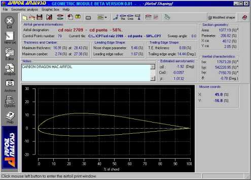
Image 3. Carbon Dragon Mean Geometric Chord.
Geometric Data of the Carbon Dragon Airfoils
|
|
Wing root airfoil
|
Mean Geometric Chord airfoil
|
Wing tip airfoil
|
|
Maximum thickness
|
19.67 %
|
16.91 %
|
14.42 %
|
|
Position max. thickness
|
31.30 %
|
28.43 %
|
20.87 %
|
|
Maximum camber
|
2.27 %
|
2.74 %
|
3.29 %
|
|
Position max. camber
|
24.55 %
|
27.30 %
|
29.57 %
|
|
Leading edge radius
|
0.68 %
|
1.67 %
|
2.19 %
|
|
Trailing edge angle
|
17.23 degrees
|
14.44 degrees
|
11.63 degrees
|
|
Geometric centroid in X
|
41.43 %
|
40.12 %
|
38.34 %
|
|
Geometric centroid in Y
|
1.56 %
|
2.05 %
|
2.49 %
|
Estimated Aerodynamic Data of the Carbon Dragon Airfoils
|
|
Wing root airfoil
|
Mean Geometric Chord airfoil
|
Wing tip airfoil
|
|
a 0 [degrees]
|
-1.27
|
-1.92
|
-2.57
|
|
Cm0
|
-0.0158
|
-0.0357
|
-0.0557
|
|
Lift curve slope efficiency factor m
|
1.0153
|
1.0132
|
1.0112
|
|
Lift slope, a0 [1/degree]
|
0.111
|
0.111
|
0.110
|
Observations regarding the geometric characteristics of the airfoils:
a) The increasing camber toward the tip should be due to a research of higher maximum lift coefficients to avoid tip stalling.
b) Progressively moving forward the maximum center position should be due to obtain earlier transition on the tip section and minimize Reynolds number effects.
c) The increase of the L.E. radius help to soften tip stall.
For the eager builder/designer:
Some remarks about the “estimated” aerodynamic data presented in AIRFOIL ANALYSIS – GEOMETRIC MODULE: The estimates of zero lift angle and zero lift quarter chord moment coefficient are obtained by the Pankurst’s method (“Theory of Wing Sections”, by Abbott and von Doenhoff) … relying just upon the knowledge of the mean line shape: it’s a sort of Gaussian quadrature and it should had been developed analytically, so no numeric is still present at this stage. The method is surprisingly good, relating to its simplicity, as you own will experience when comparing estimated to calculated data (by the numerical panel method or comparison with experiments). In fact, the flow quality on the airfoil surfaces is still “good” in the proximity of the zero lift angle (that is usually small) for conventional, unflapped airfoils … this explains why these estimates are incredibly useful even if absolutely “a priori” of any aerodynamic analysis as properly defined.
The lift curve slope efficiency factor m (the ratio of the potential flow slope to the theoretical value of 2p) is estimated according to R. Eppler (“Airfoil Design and Data”, Springer Verlag) but it’s usefulness is usually driven off by viscous effects … so practically it doesn’t matter anymore when viscous analysis are on hand.
References:
Airfoil Analysis – Geometric Module
http://airfanalysis.hypermart.net
Engineer Luca Cistriani
http://airfanalysis.hypermart.net
Carbon Dragon Technical Website - by S. Steve Adkins
http://www.isd.net/sadkins/builders.htm
Jim Maupin Ltd.
www.jcpress.com/JMaupinLtd/carbon.htm
The part II of this study will include:
- Presure distibution
- Velocity distribution
- Cl/Cd polars
- Cm/a polars
- Lift slope
Manual
Comments, notes, corrections and questions for the
Carbon Dragon Builders Manual
by Steve Adkins
Davis, Brian <This email address is being protected from spambots. You need JavaScript enabled to view it.> has created a Microsoft Word Document or an "electronic manual" which is an exact copy of the manual that is delivered with your plans.
The electronic manual is very easy to read in both electronic and printed version ... but, it allows for electronic searches for a specific item! Each page is full size 8.5 by 11 inches rather than a reduce size with 4 pages on one page as provided Maupin, ltd.
Many of the comments below have been factored into the electronic version.
Jim Maupin is able to describe a fairly complex procedure very succinctly. When I attempt to write a process, the text becomes overwhelmed by minutia. To be honest, I was dissappointed by the builders manual and extremely pleased by the drawings. On the other hand, much of the instructions are contained directly on the drawings. EAA, Chapter 25 holds a plans night about once a year and Maupin's plans (drawings) are much better than most plans sets (which are in a few cases ... one large sheet!). The drawings and handbook coupled with membership in the SHA are sufficient to enable one to create a Carbon Dragon.
The builder's manual appears to have been a preliminary rough draft; perhaps, with parts dictated to a tape recorder and transcribed by a typist ... or typed from handwritting ... thus, many errors are in the transcription process, not made by the designer. Organization leaves much to be desired ... at least one section is repeated with slightly different instructions; perhaps an updated version was slotted in without removing the first version. In any case, these errors are fairly easy to reason out and should not lead to building errors. The purpose of this section is to get new builders a fast start and to provide an exchange of information regarding corrections and comments.
Below is what I have noticed so far ... mostly nits. Much of the "changes" are adding merely clarification and headers to faciliate finding sections. In the few cases where there is a serious problem, I will highlight the text with red and a graphic like this [tbd] ... being, I'm glad we found it! One final note: The stuff below is one man's interpretation, subject to error ... if you have a better interpretation ... This email address is being protected from spambots. You need JavaScript enabled to view it.
Light red, an assumption I have made ... 3 instance
Dark red, warning about critical error ... 0 (first 16 pages)
Dark yellow, warning about known changes being made by another builder which I deem wrong ... 1 instance
Green, a question I have that is unanswered ... 2
 ... seem to be rather low numbers.
Page 3, 5th line:
Replace "wear tight" with "near right" of "near one" ... to read, "Staple ... near one edge".
Page 4, 1st line:
What part of the stabilizer is place flat on the table?
Page 4, mid page just below first drawing
Place a dividing line with the heading "Elevator" just below the line.
Page 5, mid page:
Replace "8 to 18" with "8 to 8"
Just below the "6 to 16", etc. ... I made a drawing of the tow "layers" to clarify the text description
36" 24" 16" 8" C/L
_______________________
_______________________
______________________________________________
______________________________________________
_____________________________________________________________________
_____________________________________________________________________
____________________________________________________________________________________________
____________________________________________________________________________________________
| 2 tows | 4 tows | 6 tows | 8 tows |
With each line representing 2 pulls of 12k carbon fiber tows (or yarn). This drawing represents the tow pattern for the center table of values. As you can see, from the root section or CenterLine to the 8" point, the tows are 8 deep.
Page 6, second illustration:
After counting the layer ... I decided there is a total of 7 pieces of cloth required.
Page 6, 7th line:
I might replace "Squeeze off" with "Squeege off". A nit.
Page 6, last line:
A hole for only one retention cotter pin ... I guess that is comparable to other sailplanes. Which bolt?
How do you put the cotter pin in place? ... those bolts are deep in a nicely rounded nose D-section.
Page 7, Above the title "Female Hinges", I drew a dividing line. No big deal.
Page 7, under 4th paragraph (ending with the word, " ... place"):
Draw a dividing line and add the title below the line, "Elevator Horn".
Page 10, the rudder horn
This item has puzzled many people. Jonathon Pitts wrote a dynamite article with photos and detailed decription on how to perform this construction. See Sailplane builder, September 1995, page 6. Back issues are available from SHA.
Page 11, drawings of "plug" 2/3rds down the page with labels "top view" and "side view"
After I puzzled out what these parts are ... I have had arguments with other plans holders who disagree.
The first reaction, is that these are two views of the spruce "box" (see first line of text). But, they are really the drawing of the "plug" that goes inside the box. I assume the plug is made from balsa wood. Also, be sure to note that the plug has rounded edges (see last line in first paragraph). The intent is to have a portion of the carbon spar cap to be a hollow carbon square tube. Structural engineers will attest to the stiffness of a hollow square tube ... much better than a round tube (and more resistant to denting (as when steel square tubes are used in fuselages in place of round tubes).
One builder is leaving out the plug.[tbd] I totally disagree with this change unless some other compensating change is made coupled with design analysis. A flat ribbon in this area may not be stiff enough to resist buckling under high G forces.
Also, note the upper-right most figure shows a vertical line in the spruce box cross-section. This line represent the tip of the balsa plug.
Page 12, first row of fractions:
Replace "3/5" with "3/8" ... yes, I know this is obvious!
Page 12, second row of numbers:
There should be a drawing of square under 5/16 x 5/16 similar to the two drawing to the right.
Page 12, second paragraph:
Change "larger piece" to read, "larger plug piece". ... well that's my guess ... what's yours?
Do the same in the spruce box sides?
Page 12, 3rd paragraph, 5th line:
Change "nails are" to read "nails in the plug are".
.... Time to take a break ... having fun yet? If not, wait for the carbon "pulls" for the spar cap! ....
Page 13, mid-way down the page on the right
I would replace the word "Ribs" with "Rib Numbers"
Page 13, bottom row of numbers:
Replace "14" with "15" ... also, between "23" and "19", you might want to place the total, "21"
Note: The bottom row is the total number of tows at the corresponding position in the spruce box (don't add the Rib Number into the total!).
Page 13, second figure from the bottom:
I drew a side view of the carbon material which is a long wedge shape of carbon.
Page 14, immediately under the second paragraphs ending with the word, "...curves".
Draw a dividing line. Below the line, write the heading, "Wing Ribs".
Page 14, to the left of the third paragraph:
Write "Nose" for nose ribs.
Page 14, to the left of the fourth paragraph and illustration:
Write "Center Ribs".
Page 14, draw a dividing line under the figure followed by the heading "Wing Main Spar Shear Web"
Description
Designing a Three Part Wing
The original Carbon Dragon, as designed by Jim Maupin, had a two-part wing joined at their root, at the centre-line of the glider. With a full wingspan of 44 feet, this means that any trailer built to haul the glider around would have to accommodate two 22 foot long wings - not only unwieldy for a single person to handle and assemble (especially in a breeze) but also likely to incur extra charges every time the glider is taken by ferry to the continent from Ireland. Splitting the wing into three sections would reduce the longest component to around 15 feet.
A number of issues arise when considering a three-part wing:
Where to split the wing:
If we split the wingspan roughly in three, each section will be 14.66 feet (or 176 inches) long. It makes sense to split the wing just outboard of the nearest rib. So if our centre section of wing is approximately 176 inches long, dividing this dimension by 2 (half, either side of the centre line of the glider) we get 88 inches. Looking at the drawings, Rib #5 is closest to 88 inches outboard of the root, 94 inches out from the centre-line. The total length of the centre section of wing is therefore 94 x 2 = 188 inches or 15.67 feet long. The length of the two outer sections of wing then become 44 feet less 15.67 feet = 28.33 feet divided by 2 = 14.165 feet or 169.98 inches long.
Dihedral:
Dihedral must be built into the centre section of the wing if we are to maintain the inherent stability of the design. We can work out the amount of dihedral by carefully examining and measuring the drawings.
On Drawing #1 we see that the wingspan of the glider is 44 feet, so one wing length, root to tip is 22 feet or 264 inches.
Drawing a line perpendicular to the vertical centre-line of the glider, from the vertical midpoint of the spar-web at the root out to the vertical midpoint of the spar-web at the wing tip, we can measure how much higher (dihedral) the centre-line of the wing tip is above the centre-line of the wing root. I measure this as 12/64ths (or possibly 13/64ths) of an inch... approximately!

Ignoring the scale given on the drawing (because the printout of the drawing from the PDF file cannot be trusted) we can derive the true scale by dividing the wingspan dimension indicated on the drawing (44 feet or 528 inches) by the physical measurment of the drawing of the same dimension (16.75 inches). Thus the true scale of the printed out PDF drawing is 528 / 16.75 = 31.522x.
Multiplying our 12/64ths of an inch by the correct scale, 31.522, gives us the slightly odd dimension of 5.9 inches. Given the thickness of the lines on the drawings, it is difficult to get an exactly accurate measurement, and we could easily be out by more than 1/64 of an inch, and indeed Steve Adkins reckoned it to be 6 inches exactly, which seems not unreasonable.
Steve Adkins notes: "As to the dihedral: dihedral is provided by building the lower spar cap 0.25 inches longer than the top spar cap. The assembly pins are 11 and 5/64th inches apart at the bolt centers. From this, you can calculate how much a wing tip would be raised. I am thinking the center line of the wing tip would be raised nearly 6 inches above the wing root center. One builder mentioned to me he was going to build a flat wing which I discouraged (I wouldn't second guess Irv Culver)."
With this new dimension quantifying the dihedral built into the wing (how much higher the centre of the wing tip is to the centre of the wing root) we can, by simple trigonometry, work out the angle at which the wings tilt up from the vertical centre-line of the glider. This angle is 1.3°. It is critical to know this angle when it comes to laying out and fabricating the centre section of a three part wing.
Spar Cap Root Junctions:
Attention need to be paid to how we treat the stresses on the upper and lower spar caps where they come together at the root. The pultruded carbon rods used in the spar caps will not bend at the root / centre line to accommodate the 2.6° (2 x 1.3°) of dihedral built into the centre section of the wing. [NB: actually the rods *will* bend to accommodate the built-in dihedral, as I later discovered, but an unbroken bundle of rods does make the lay-up and bagging process a bit trickier] The bundles of rods must therefore terminate at the centreline and a load transfer bar must be designed and incorporated.
In designing the load transfer bars which transfer the spar cap loads from the carbon rods to the wing root metal fittings for a two-part wing we calculated that the bar must have a minimum thickness of 0.184". The 284 Twill Carbon Fibre cloth I am using has a thickness of 0.011" per laminate, so therefore we need a minimum of 0.184 / 0.011 = 17 layers of cloth in our load transfer bars (for both upper and lower spar caps) spanning the space between the two root ribs.
It would do no harm (and add little weight) to beef up the centre section of the spar web, between the two root ribs, to make the whole assembly a little more robust. One way to do this is to sandwich a plate of 5mm thick PVC foam board between the root ribs and the upper and lower spar cap load transfer bars. As luck would have it, 0.184" = 4.67mm thick, so by adding just one more laminate of carbon cloth to our load transfer bars (making them 18 laminates thick) will allow us to create a perfectly flush surface between the root ribs and the spar caps of the centre section!
Note: When the centre section of the three-part wing is not connected to the rest of the glider (i.e. during rigging / de-rigging and transport) the root section of the spar will be liable to experience large bending forces if it is not properly braced and supported at the drag spar connection points, and there is a very real possibility of damaging the spar. Inserting a short beam of plywood between the drag spar connection fittings will prevent the spar from bending in the wrong direction.
Wing connections:
Splitting the wing at a rib position allows us to close off the ends of the centre section of the wing by incorporating a blanking plate into the rib to prevent dirt and insects from getting in. By replicating this rib (Rib #5) we can also close off the outer sections of wing also and provide a solid mating surface to the two parts of the wing. As we will see below, the wing connection fittings and load transfer bars will need to protrude through all of these wing section end ribs.
While we can safely use the 17 layer (minimum) load transfer bar to transfer the loads from the spar caps across the root section of the wing, the loads on the wing spar caps and shear web are considerably less when we move outboard along the wing. At Rib #5, where we plan to split the wing, the loads are considerably reduced (less than half) from those experienced at the root. It is sensible, therefore, to recalculate and redesign the load transfer bars and the metal wing connection fittings so that weight can be saved where possible.
Redesign the connection fittings and method...
(to be continued...)
Flaperons:
Joining the sections of flaperon - maintaining stiffness!
(coming soon...!)
Analysis
Click here to download an archive of Phil Lardner's 3-Part Wing Analysis
Air Brakes
THIS ARTICLE IS INCOMPLETE - check back later... possibly much later!
I am investigating the possibility of replacing the single delta shaped spoiler, behind the pilot's head, with proper Schempp-Hirth air brakes inside the wings, just inboard of Rib #5, and just outboard of the H-Stab to elimenate any interference (by turbulated air) with the rudder and elevator. I have a basic design concept on paper but it has yet to be prototyped and load tested up to and beyond Vne by attaching it to the roof rack of my car and driving it up and down the motorway! I will need to construct a small section of wing (leading edge, wing spar and trailing edge...) between Ribs #4 and #5, where the air braek will be fitted, so that both the air braek and the wing section (against which the braek forces will react) can be tested to see how they perform.
http://en.wikipedia.org/wiki/Air_brake_%28aircraft%29
Although this type of air brake will probably add a little weight to the glider overall, I want my Carbon Dragon to have a cockpit layout that will be familliar to any sailplane pilot. I also believe that the new Schempp-Hirth brakes will be easier to use with greater finess. Some pilots report the original delta shaped spoiler is difficult to open fully at higher airspeeds. Maintaining a constant glide slope requires accurate and fine adjustment of the air brakes - something not possible with the original delta spoiler.
(Details coming soon...!)
Tail Boom
I am making the tail boom removable from the pilot pod - this requires a new attachment method using high shear strength pip pins.
I am making the tail/rudder removable from the tail boom for more compact transport - this requires a new attachment method using high shear strength pip pins.
Both of these changes will also require modification of the control wire system for the rudder and elevator.
Details coming soon...
Contest!
Contest for the Purchase of the Last Plans Set
[Revised 7/12/2004]
A contest is being conducted to see who bought the last set of plans from the Maupins; and thus, has the highest serial number. The prize is publishing your number and a link. Thanks to Steve for not only sending in his serial number, but sending a photo of his plans canister with the serial number. Due to some kind of mix up on my part, I used Steve's letter but attributed it to another builder.
Please be aware this is the fourth "Steve" involved with the Carbon Dragon:
Steve Rappe ... buildingStéphane Abbet ... completeSteve Arndt ... complete (Magic Dragon ... renamed due to modifications)Steve Adkins ... no longer building
Please include Name, address, email, Serial Number and Intentions to build, study or modify.
Update from Winner - Steve Rappe with Serial No. 476
Subject: plans number 476
Steve Rappe of Ft. Mill S.C.
This email address is being protected from spambots. You need JavaScript enabled to view it.
Steve writes ......
Hi Steve,
I was just examining your new Carbon Dragon page and noticed you updated the plans sold to number 473. I can only imagine you are serious about the number sold. ... snip ... Anyway here is a photo of my canister.
I'm still working on building space but have a hope to build the Cd or a derivative.
|
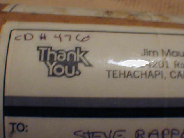 |
Usually, being first decides the winner, but in this case ...the Winner for the CD contest is last ... holding the highest serial number is ... #473
|
Steve Rappe
Email, Tue 2/4/2003 1:29 AM ....
Hi Steve,
I was the last person to buy plans from Margaret Maupin. I received an email stating that they no longer sold plans - after mine were paid for! I replied to the email and found out I wasn't supposed to get it. My set was the last sold. Serial number is 473.
|
Too bad, seems to be quite a demand for the plans, even if it is just for study (like myself). I'm still getting some design work done on my derivative design, but starting up a new business has slowed progress considerably. Hopefully by late fall, I'll be ready to start making molds and parts.
Note: Jim Maupin hoped for derivative designs.
|


