Welcome, Guest
Username: Password: Remember me
  • Page:
  • 1
  • 2

TOPIC:

Rudder spar dimensions incorrect on drawing #4 03 Oct 2014 18:13 #833

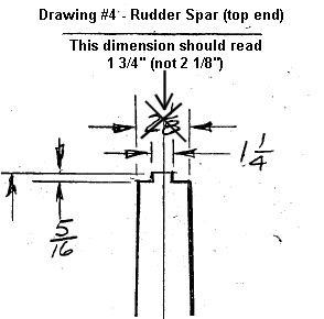
One of the dimensions of the rudder spar on drawing #4 is incorrect.

Drawing #4 shows the width of the top end of the spar to be 2 1/8", which is too wide.

It should read 1 3/4".

All the other dimensions on the drawing are correct.


Hi Rick,

A quick question...

I am currently assembling my rudder (gluing the hinges, hinge supports, D-section formers, etc.) to the rudder spar and have just discovered that four of the six triangular ribs are are not the same width as the spar where they are supposed to be bonded to it.

I have double checked my spar and its physical dimensions are exactly as specified in the plans. The ribs were made using the plans as a template and my ribs match the plans with better than 1mm accuracy but I am at a loss as to why there is a growing disparity in the with of the ribs as you go up the spar:

Rib# Spar Width Rib Width Difference
6 54mm 44.5mm 9.5mm
5 63mm 58mm 5mm
4 72mm 69mm 3mm
3 82mm 79mm 3mm
2 92mm 91mm 1mm
1 102mm 103mm 1mm

Rib #6 is particularly bad - the spar is 54mm (2 1/8") wide at the top but the width of the rib where it joins the spar is 44.5mm (1 3/4") - there's no way this can be a scaling error on my printed plans! What am I missing???

Did you encounter a similar problem or did your ribs match the dimensions of the spar exactly? I've checked the scale of my drawings and it is close enough to the correct scale that this does not account for the error.

If you have a moment could you take a look at drawing #4 and measure off the width (base) of each of the triangular rudder ribs and the width of ribs #5 and #6 where they intersect with the spar?

I'd really appreciate this!

Phil.

Rick replies: "Yeah, you've discovered one of the many errors in the plans. The drawings show the overall width as 2 1/8 and the space between the rib stringers as being 1 1/4 inch. However the rib stringers are made of 1/4 spruce and 1 1/4 plus 1/4 plus 1/4 equals 1 3/4. I made notes in my plans when I found errors but missed marking this one."

Attachments:

Please Log in to join the conversation.

Last edit: by Phil Lardner.

Details of various errors in the drawings. 03 Oct 2014 18:25 #834

Following on from the error on drawing #4 of the rudder spar top end, Rick Mullins highlights a few more errors he found the hard way:

Yeah there were a few parts I remade because I didn't catch the errors soon enough.

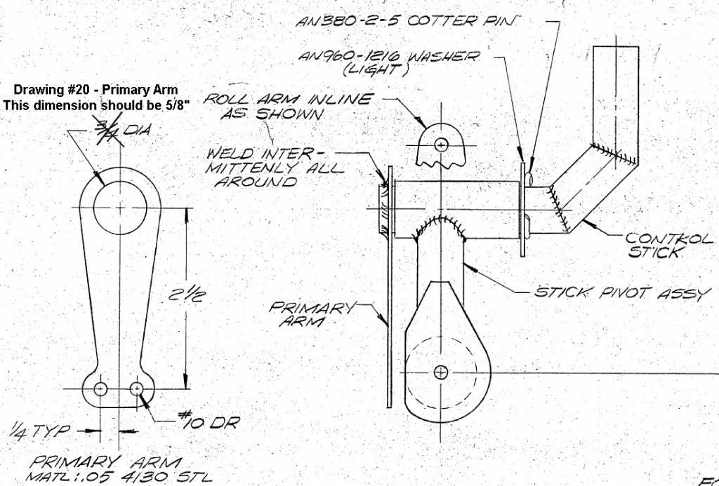
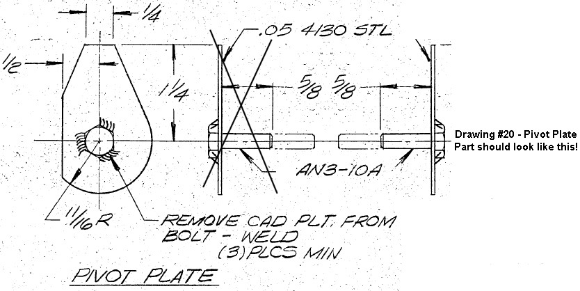
When you get to the control stick and pivot assembly on sheet 20 you'll see he must have been having a bad day. I made those pieces and welded them wrong 2 times before I caught it.

The left drawing of the pivot plate shows the head of the bolt and the flat side to the left. All the other drawings show the shaft side of the pivot plate with the flat side still on the left.

If you are looking at the pivot plate on the bolt head side, the flat side should be to the right, the left drawing is wrong.


Also the control stick is made of 5/8 steel so the hole in the primary arm should be 5/8, not 3/4 as shown in the plans.


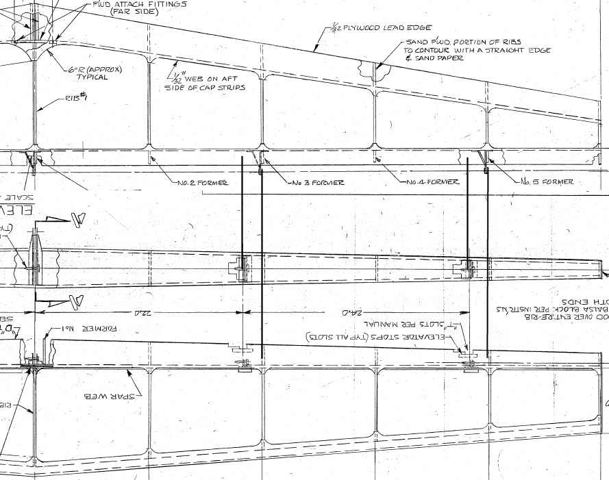
The other big one that comes to mind is when mounting the hinges for the elevator to the horizontal stab, on the stab the hinges are lined up with ribs, on the elevator the hinges are shown shifted, they won't line up.

Attachments:

Please Log in to join the conversation.

Last edit: by Phil Lardner.

Details of various errors in the drawings. 16 Oct 2014 10:09 #840

One more error for the pot!

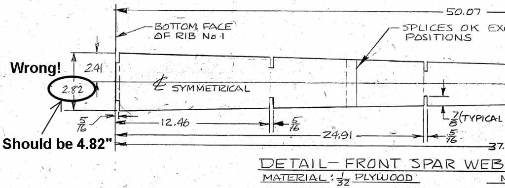
Drawing #3 shows an incorrect dimension for the lower end of the vertical tail fin front spar web. The half-width of the spar web is correctly shown as 2.41" but the full width is incorrectly shown as 2.82". It should read 4.82".


Note also that the spar caps extend beyond the bottom of the spar web. The spar web is 50.07" long but the spar caps need to be 58 13/16" (58.8125") to reach down the sides of the tail boom as they taper off. This is important to note if you are laying up this spar using composites and carbon rod for the spar caps - don't leave yourself short (like I did!) Also, the reinforcement plate at the bottom of this spar can be incorporated into the spar during lay-up. I pre-fabricated my reinforcement plate out of 5mm foam board with five layers of carbon cloth either side.

www.ihpa.ie/carbon-dragon/index.php/cd-b...#tail-fin-front-spar
Attachments:

Please Log in to join the conversation.

Last edit: by Phil Lardner.

Rudder spar dimensions incorrect on drawing #4 13 Jan 2015 20:37 #856

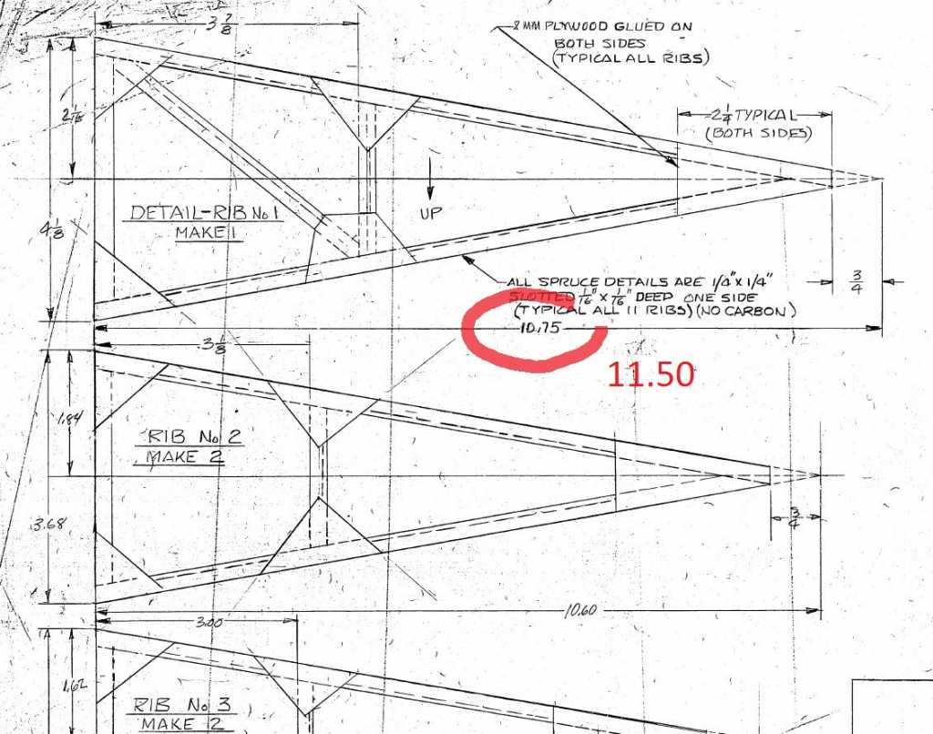
Dimension of the elevator rib N°1 is incorrect on plan N°6

This is for proportionnality with other ribs. 11.50" match with the measure on plan.

*** CAUTION *** This modify the surface of the elevator.


Attachments:

Please Log in to join the conversation.

Rudder spar dimensions incorrect on drawing #4 13 Jan 2015 23:45 #857

Well spotted Bertrand - thanks for posting that one!

I've added the details to the list here: carbon-dragon.ihpa.ie/index.php/home-top...#errors-in-the-plans

I'm actually working on my H-stab and elevator at the moment. Thankfully I used the drawing itself as a template and my ribs are all the correct size!

All the best,

Phil.

Please Log in to join the conversation.

Last edit: by Phil Lardner.

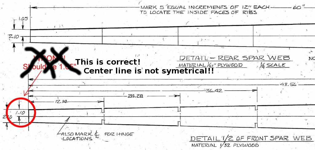
Horizontal Stabiliser Front Spar - Drawing #5 - Incorrect Dimension - (Actually, it *is* correct!) 27 Jan 2015 12:08 #863

EDIT: My mistake! The drawing does indeed show the correct dimensions for the outer ends of the H-Stab front spar. The 'center line' shown is NOT in the geometrical center of the spar but is indeed offset. The dimension above the line is indeed 1.1" (1 3/32") and just 1" below the line.

Drawing #5 - The half-width dimension of the horizontal stabiliser front spar is incorrectly shown as 1.10". This should read 1.05".


Attachments:
The following user(s) said Thank You: Andrey Serdyukov

Please Log in to join the conversation.

Last edit: by Phil Lardner.
  • Page:
  • 1
  • 2