Welcome, Guest
Username: Password: Remember me

TOPIC:

Progress on Phil Lardner's All-carbon CD? (Part 1) 22 Jun 2017 22:23 #1044

I forgot to add...

Ouch! :huh:
The topic has been locked.

Progress on Phil Lardner's All-carbon CD? (Part 1) 22 Jun 2017 22:53 #1045

Oh man, you have to be sick. I can't quite figure out how you have the two wings fastened in the center, it looks like you didn't use the aluminum plates the plans described. At least it does look repairable without too much grief and it happened on the ground.

Still, that really sucks...
The following user(s) said Thank You: Phil Lardner
The topic has been locked.

Progress on Phil Lardner's All-carbon CD? (Part 1) 23 Jun 2017 02:08 #1046

My aluminum cap joints at that location are 4 of 7075-T6 .125x 1 top and bottom, total of 1/2 thick top and bottom. That is only at the very center where there are no spar cap, slightly outboard the root spar caps are an additional 1/4 buildup top and bottom. If you want my drawings let me know.

I will add that 7075-T6 has a compression yield of Fcy = 66,000 psi, which is a fair amount higher than 6061-t6 at 35,000psi or 2024-t3 at 39,000 psi.
The following user(s) said Thank You: Phil Lardner
Last edit: by Don B.
The topic has been locked.

Progress on Phil Lardner's All-carbon CD? (Part 1) 23 Jun 2017 06:59 #1047

Ouch is right!
I am so sorry about that. I hope you get it sorted without too much trouble.
The following user(s) said Thank You: Phil Lardner
The topic has been locked.

Progress on Phil Lardner's All-carbon CD? (Part 1) 23 Jun 2017 10:19 #1048

Rick Mullins wrote: I can't quite figure out how you have the two wings fastened in the center, it looks like you didn't use the aluminum plates the plans described.


Hi Rick,

I've made a three part wing, with the centre 16' span all in one piece. I don't (didn't) have any metal brackets at the root of the wing as in the original drawings, but instead laminated in a pair of thick carbon load transfer bars between the two #1 ribs. These have the strength (on paper!) to carry the compressive and tensile loads... but I clearly didn't take compressive buckling into account.

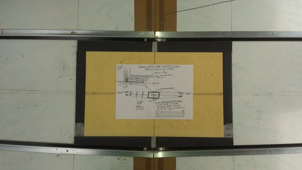
Here's a drawing of how the centre, root section was laid up:


The spar cap flange between the two #1 ribs is only 10mm deep and is unsupported by the leading edge skins. In hindsight, this was an obvious point of failure. My fix is to bolt a pair of 10mm aluminium plates to the upper spar cap (front and back), through the solid carbon LTB, and another one on the lower spar cap LTB just for good measure.

Watch this space...!
Attachments:
The topic has been locked.

Progress on Phil Lardner's All-carbon CD? (Part 1) 23 Jun 2017 11:08 #1049

I can help you as regards Aluminum, however I do not know CF. A critical specification is the Bearing Strength of the Carbon.
My Carry Through is stressed for 12G.(5.33x1.5 ultimate x1.5 FOS) I do not know what the original is stressed for. That the 3/16 in the original in wood is strong enough I did not check. Larger bolts 3/8 for example would accommodate smaller bearing strength if Carbon bearing was less than Aluminum. 1/4 is what is shown in my drawing.

The drawing also shows the attachment to the round fuselage tube in my bird....much different than the original.
Attachments:
Last edit: by Don B.
The topic has been locked.