The devilishly handsom dude, above, is me - Phil Lardner. I've been flying flex-wing hang gliders in Ireland and around the world since 2000 and, for my sins, have been the Training and Flight Safety Officer for the Irish Hang Gliding & Paragliding Association for much of that time also. Flying is one of the great passions in my life... and like most of my other passions, I ain't getting enough of it! So to keep my impishly inquisitive hands busy and out of mischief I decided to build myself a Carbon Dragon. My decision to go for a Carbon Dragon was partly dictated by lust and partly by pragmatism - I wanted something with a lot more performance than a hang glider but without the regulation, licencing and price tag of a sailplane!
Enter the Dragon...
The original Carbon Dragon, by Jim Maupin with airfoils by Irv Culver, was designed to be built out of spruce, 1/4" mahogony plywood and 1/32" (0.8mm) plywood, reinforced here and there with the judicious use of carbon fibre rovings bonded to the wood. The prototype CD, now owned and flown by Gary Osoba, was a masterpiece of minimalism - Jim Maupin's philosophy in building the Dragon was "if you want to add to or change the design, first take it outside and toss it up in the air. If it comes down... it's too heavy!"
Spruce and plywood are incredible materials - their strength to weight ratio is very hard to beat. It's easy to make something stronger, but it's very difficult to make it stronger and lighter. Even modern composites struggle to beat natures own wonder materials. Where spruce and thin plywood do fall down is when it comes to humidity. Wood is naturally hygroscopic - that is to say, it absorbs and releases moisture depending on the relative humidity of the atmosphere around it. Over time, the thin (0.8mm thick) plywood leading edges of the flight surfaces begins to deform and go out of shape and, as a result, looses aerodynamic efficiency and strength. Ireland, sadly, is not noted for its dry, desert-like climate, so building such a light, flimsy glider out of wood in this country is probably not the smartest idea!
Various builders have replaced some of the wooden parts with composite materials to a greater or lesser extent. No one, as far as I could make out, had ever built a Carbon Dragon entirely out of carbon fiber, or had done a thorough analysis of the loads and stresses on the wings and airframe. If I was going to build one of these gliders and fly it, then I certainly wasn't going to trust life and limb to a lot of guess work and wishful thinking. I wanted to know exactly how strong each individual part and assembly of the glider needed to be and I was going to verify those numbers through destructive testing first...
Later incarnations of the Carbon Dragon, with Steve Arndt leading the way with his beautiful Magic Dragon, replaced the wooden wing spar caps with much stronger and lighter pultruded carbon rod. However, when I started seriously looking at the Carbon Dragon, there was no information about how much of this new wonder material was to be used, so I decided to analyse the loads and stresses on the wings from scratch. You will find a record of my calculations, along with an interactive spreadsheet into which you can enter your own design criteria, on my Wing Stress Analysis page.
As my study of the design progressed and I learned more about the strengths of carbon fibre cloth, I decided to fabricate the leading edges out of two layers of carbon twill cloth laid up at 45°. The carbon leading edges will likely turn out slightly heavier than the original 1/32" plywood skins, but they will be much stronger and not subject to warping in humid conditions. I hope to save weight else where to compensate. [Note: Rick Mullins talked to Steve Arndt about the construction of his Magic Dragon. Steve says that he built carbon fibre leading edge D-skins for his wings and has successfully towed behind an airplane at speeds in excess of 70mph with no sign of wing flutter.]
The original wing ribs were fabricated out of 5/16" x 1/4" spruce, reinforced at the joints by 1/32" plywood gussets. These looked very fiddly to make up and would require the rib caps to be steamed and formed if they were to assume the desired curves accurately. After some experementation I arrived at a method for fabricating ribs out of 5mm PVC foam, wrapped and fully encapsulated in carbon cloth. These carbon/foam ribs performed extremely well under load testing. A full report on the rib fabrication experements and load tests can be found on the Rib Construction page. My aim is to completely eliminate the use of wood in my glider and (hopefully) to end up with a stronger and lighter aircraft.
Design Criteria
The design load-limit for my wing is +8g / -4g at a maximum pay-load weight of 260lbs. The ultimate load limit (catistrophic failure point) is +10.5g / -7.5g. Both sets of figures may seem to be overkill, and indeed it is not anticipated that the glider will ever experience more than +2g or possibly +3g in flight, but account most be taken of the instantaneous shock-loads that the glider may experience during ground handling, launching and especially during a rough landing! You can view the full details of the design weights and loads I used in my wing stress analysis spreadsheet.
Playing with Gerolf Heinrichs' Moyes Malibu at Monte Cucco in Italy during the 2009 Hang Gliding Pre-World Championships Sensational legs, huh?!
Wing Stress Analysis
Analysing the Loads and Stresses Along the Wing
My wing calculations are based on the formulae and method described in Jim Marske's Composite Design Manual. If you don't yet have a copy of this manual then I strongly recommend that you buy a copy, even if you don't intend to do the calculations yourself for your own design loads - it contains a large amount of practical knowledge about working with and fabricating composites. The photos, below, are of my initial hand written calculations, refrencing the appropriate pages in Jim Marske's manual, and show the formula and description of the method used to arrive at the numbers in my spreadsheet.
Download my spreadsheet here - it summarises all the calculations below and allows you to enter your own initial design loads to see what effect they have on the various parts of the wing.
I designed my Carbon Dragon to my own specific load criteria. I take absolutely no responsibility or accept any liability whatsoever for any adverse consequences should you build your own Carbon Dragon to the same design configuration as detailed in my calculations or for using my spreadsheet and any design numbers that you may obtain from it by modfying the initial circumstances. You use my calculations and spreadsheet entirely at your own risk.
I've been a bit quiet recently but that's because I've been busy trying out different rib fabrication techniques and testing them. It's been an interesting learning experience and I think I've arrived at a formula that I'm happy with for constructing production parts for my Carbon Dragon. Please forgive the long post, but I want to give as much information as possible to give a clear picture of what I did and how I did it. Comment and constructive criticism are welcome!
You will find all the photographs referenced in this post in my photo album within this group - It might be worth having these photos visible in another browser tab while you read on...
My initial attempt to build a carbon wrapped foam core rib was an unhappy success - it worked (surviving 8g load testing) but suffered badly from bridging along all the edges, which I had to grind off, exposing the foam core. Although the rib survived 8g load testing it exhibited too much bowing and distortion for my liking. This rib was was made without any moulds by laying a 5mm thick closed-cell PVC foam cut-out of the rib (with caps and internal braces 25mm wide) directly onto a hand-wetted single layer of CF Twill cloth, with another single layer laid over this. A layer of perforated release film, followed by a layer of breather fabric and finally the vacuum bag film was placed over the lay-up, and a vacuum drawn down. Despite my best efforts, and working against the clock (before the epoxy started to gel) I found it impossible to get all the layers to conform perfectly to the foam core and there was an unacceptable amount of bridging on all the internal angle edges.
Given the extraordinary length of time it took me to lay-up this one rib using the wet lay-up method I decided to switch to using the Vacuum Assisted Resin Infusion method instead as it allows you as much time as you need to get the lay-up perfect before you even start mixing the epoxy. The Resin Infusion method, in my opinion, is infinitely superior and safer than the wet lay-up method. I will be using the Resin Infusion method from now on for all my parts.
It was suggested, after my first test report a few weeks ago, that I try increasing the thickness of my foam core (and reducing the depth of the caps and struts) to improve the stiffness of the rib, so I constructed my next root rib test piece out of 10mm thick closed-cell PVC foam board and also reduced the cap and internal strut depth to just 10mm. The weight of the new rib remained about the same as the 5mm thick rib. Again I was plagued by bridging along all the edges where the upper layer of cloth came down to meet the lower layer of cloth on the flat work surface. The foam core was exposed in places after the part was trimmed, but ended up weighing more than the first 5mm thick rib due to the excess resin concealed within the untrimmed bridges - not a pretty sight.
Root Rib 10x10mm foam core - close up of bridging problem
Root Rib 10x10mm foam core - after debagging - detail of bridging problem
Root Rib 10x10mm foam core - detail of bridging - foam core not fully encapsulated
Surprisingly, when this 10mm x 10mm rib was mounted on the test stand and loaded to 8g it exhibited an unacceptable amount of twisting and bowing - far more than the first 5mm thick rib - although it did survive to 8g loading.
Root Rib 10x10mm foam core - load testing set-up
Root Rib 10x10mm foam core - twisting under moderate load
I was not happy with this rib at all... but mostly I wasn't happy with the method of construction, which resulted in unavoidable bridging and excessive weight. A new method of construction was plainly needed if I was to overcome the bridging problem.
For my third root rib test piece I went back to using the 5mm thick foam core, but reduced the cap and internal strut depth from 25mm to 24mm wide and constructed it using a male mould. The male mould was made out of 12mm thick MDF sealed with around 5 or 6 layers of thinned out polyurethane floor varnish - fine sanded between coats to provide a high gloss finish to the mould, which was then wax polished and treated to a coat of PVA release agent.
Main Wing Root Rib - mould blank marked out
Main Wing Root Rib - corner curves are created using a 24mm flat 'spade' drill bit
Main Wing Root Rib - finished male mould
My thinking behind using a male mould was three-fold: firstly I wanted a means to fully encapsulate the foam core; provide the rib with a 10mm wide flange all around its outer perimeter (and a 5mm flange along all the internal strut edges to reduce bowing under load), and finally to remove the problem of bridging... or at least move the bridging to an area of the part that would get cut away during the finishing process. This worked very nicely, as can be seen in the following image:
Main Wing Root Rib - detail showing the peripheral and internal flanges
This rib was load tested to 8g (32.55kg) and performed very well, with only a little twisting and bowing of the part under full load. Unfortunately the plywood batten I had glued the rib to (for mounting onto my test stand) delaminated and sent the whole lot crashing to the floor - water everywhere! However... the rib survived!
As this new rib had performed so well I decided to grind off the 5mm flanges from the internal edges of the caps and struts; the edges of the foam core remain fully encapsulated in CF cloth. With that done, and the rib a few grams lighter, I re-glued the rib to a fresh piece of plywood and put it back on the test stand.
The second test of this rib also went very well, again surviving 8g loading with only slightly increased twisting and bowing now that the internal flanges had been removed. My plan now was to increase the load incrementally until the part failed. Unfortunately, again, the plywood batten the rib was glued to delaminated at around 9.5g leaving me with another small ocean to mop up off the kitchen floor! However, I think I have proven that the new rib configuration is more than successful - I will re-test this batten yet again to discover exactly at what load it fails. Watch this space.
On the strength of these tests I now plan to use a 5mm thick core for all my wing, tail and H-stab ribs. The root rib of the main wing has caps and internal struts 24mm wide and I plan to reduce this dimension by 2mm for every rib as you move out from the root - so, rib #2 will have caps and struts 22mm wide, rib #3 - 20mm wide, rib #4 - 18mm wide, and so on down to rib #8 which will be reduced to just 10mm wide. At this point the 5mm thick foam becomes too delicate to to cut and sand without damaging it before lamination. So, at the same time that I made the second 5mm thick root rib I also fabricated a #8 rib for testing - again, using a male mould.
The test loads for rib #8 are 2.81kg at 1g, 14.04kg at 5g and 22.47kg at 8g, but holding the rib in my hands and hardly able to feel its weight I seriously doubted that it would survive to 5g let alone 8g - having run the numbers, I was conscious that I was reducing the depth of the rib caps and internal struts faster than the load was being reduced out along the wing. However, not only did it survive to 5g with only minor twisting, it survived 8g loading without complaint!
Wing Rib 8 Load Test - under full 8g load
Wing Rib 8 Load Test - under full 8g load
I left the rib loaded to 8g (22.5kg) while I went off for a cup of tea and came back to find it still smiling happily, so I continued to increase the load until it finally failed at just over 28kg, a load of 9.97g!!
Wing Rib 8 Load Test - failure of part under 9.97g (28kg) load
Wing Rib 8 Load Test - close-up of failure mode
Satisfied with these results (though not 100% happy with the male moulds, which are reluctant to release their grip on the part being fabricated) I turned my attention to the wing tip rib (rib #13) which requires its outboard surface to be fully covered and the flange around its outer perimeter to point back inboard instead of outboard like the rest of the ribs (the root rib particularly.) I decided to try fabricating a female mould for this part and use the foam core, carefully sanded to an exact fit, to gently press the CF cloth into place.
The results were astounding. Where I had spent nearly an hour trying to get the various layers of CF cloth, peel-ply, flow-media/mesh and vacuum bag film to conform to the complicated internal geometry of the root rib and rib #8, it took me literally two minutes to assemble the laminate stack for the tip rib. Sealing the vacuum bag with gum tape and pleats took another ten minutes, but when I applied the vacuum, the whole part conformed to the female mould perfectly - and I do mean *perfectly*! The resulting part, once it was trimmed and finished was flawless... and weighed in at only 21grams!
Wing Tip Rib - female mould and 5mm thick foam core
Wing Tip Rib - foam core is a tight fit for the female mould
Wing Tip Rib - foam core pressed into the female mould over the first layer of CF cloth another layer is laid over this to complete the lay-up
Wing Tip Rib - vacuum bagged and infused with resin
Wing Tip Rib - part released from mould - perfect!
Wing Tip Rib - inside view - all trimmed and finished
Wing Tip Rib - outside view
Although this was only supposed to be a test part, it is more than good enough to keep and use as a production part.
The female mould has proven so easy to use (though more care is needed to sand the foam core to an *exact* fit) that my next job is to fabricate yet another root rib, but this time using a female mould.
I also want to experiment with using a white epoxy pigment so that I end up with a more heat-reflective (less heat absorbent) part than the standard black carbon fibre. When flying hang gliders in the French Alps during summer, the carbon fibre cross-booms become almost too hot to touch even though they are protected inside the glider's sail - one can only hope that they have been post cured to a high enough temperature! The post curing regime that I have for the infusion resin that I am using takes it up to 80degC. I haven't enquired if this can be increased to >100degC.
The one draw-back of the female mould over the male mould is that you need to fabricate separate moulds for both the left and right wing components, and so doubling your work - no big deal if you're handy and careful with a router! I'll take a few photos of the process of making a female rib mould and report back.
So far, so good - Phil is a happy boy!
You can read the follow-up discussion to this article >>>Here!<<<
Rib Fabrication
Below is a step by step photographic description of how I fabricated the main wing ribs. I arrived at this method after some trial and error. It is a simple, inexpensive and workable solution to wrapping thin PVC foam cores in carbon fiber cloth. Unless otherwise mentioned elsewhere, I have used this method for all the ribs and parts used in my build.
The rib templates are first traced off the original full scale drawings onto grease-proof paper (kitchen baking parchment) before being laid out and taped down on to 1/2" thick Medium Density Fiberboard (MDF) using decorator's paper masking tape, which is easy to remove.
A wide, flat felt tipped marker pen is used to trace around the template, inking both the edge of the template and the MDF. When the template is lifted the inner edge of the black marker line is sharply defined by the edge of the template.
With the outlines marked out, the internal ribs are now drawn in using a fine tipped pen or pencil.
The parts are roughly cut out using a jigsaw, taking care not to let the blade wander inside the black marker line.
Once cut out, the parts are carefully sanded down to the inside of the black marker line using a bench mounted high-speed disc sanding machine.
Each part is carefully adjusted (by continued sanding) until it perfectly matches the original plans.
The machine sanding process creates a lot of very fine dust. It is essential to wear a full face breathing mask as the dust and formaldehyde in MDF can cause serious heatlh problems later on in life. Don't take any risks with your health - it's not worth it.
A general purpose router is equipped with a specially built jig/fence to cut a 5mm deep rebate. This rebate should be exactly the same depth as the thickness of the PVC foam core you will be using.
The width of the rebate can be set by adjusting the depth of the router plunge. The depth of the rib caps and internal struts starts at 24mm at the root rib and is reduced by 2mm at each rib out from the root until rib #8, after which the remaining ribs (#8 to #13) are just 10mm deep.
The perimeter of the sanded rib mould blanks are routed to form the 5mm deep rib caps. This is a really quick and easy job... very satisfying!
Here's how the rib mould looks after the perimeter has been routed.
The router (with it's bespoke base plate jig) is clamped to the work bench... with another small G-clamp gently pressing down on the power button!
Close-up of the router and jig set-up.
The rebates for the internal, diagonal struts are cut using the router running against a simple fence pinned to the surface of the MDF.
Same as above - just from a different direction!
The finished rib mould - ready for fine sanding and varnishing,
The rib moulds are fine sanded and given up to five coats of polyurethane gloss varnish to seal the MDF. I was able to speed up the drying time between coats by using the convective heat from my Aga range cooker!
The finished moulds are next laid out on a 1m x 1m square sheet of 5mm thick closed cell PVC foam board, taking care to fit as many parts as possible onto a single sheet of the foam. A ball-point pen is used to trace around each part.
With the parts traced out on the foam board, a very sharp Stanley knife (craft knife) is used to cut out the parts free-hand. The parts are cut out taking care not to let the knife wander inside the ink perimeter line. Each foam part will be fine tuned to exactly match its host mould later on...
More rib moulds... Note the unvarnished #2 rib. This rib is bisected by the drag-spar and at this stage I haven't decided exactly how I will do this junction.
All the foam rib blanks roughly cut out - note that you can still see the ballpoint pen marks around the perimeter.
Three or four pieces of double sided sticky tape are used to attach the foam blanks to their respective MDF moulds. The foam is then trimmed using the router to make it exactly the same size as the mould.
After trimming with the router, the PVC foam and MDF mould are exactly the same size and shape!
Once trimmed, the foam is carefully removed from the MDF, taking care not to damage either. The pieces of double sided sticky tape are removed and discarded.
The next step is to carefully mark in the internal struts. The curved rib caps are easily marked in by gently scoring the foam using an adjustable carpenters gague.
A very sharp knife is used to cut out the excess foam between the internal struts. Care should be taken to make the foam a very tight fit for the mould. It will be carefully sanded to a slightly looser fit next...
A useful tool for sanding the foam internal struts so that they fit the mould is a piece of fine emmery paper stuck to a scrap of wood or aluminium strip using double sided sticky tape. This ensures that you can sand the foam perfectly flat and evenly... something not possible if the emmery paper is just loosly held in your fingers!
The finished foam core, sanded to a perfect (but not excessively tight) fit for the MDF mould. Now repeat the process for all the other 25 ribs!!
Patients, care and attention to detail are rewarded with a perfect set of foam rib cores!
Don't they look great!
The next step is to apply three coats of parting wax and a coat of PVA parting compound to all the moulds, taking great care to ensure that you reach all the internal angles and corners of all parts of the moulds - miss a bit and the part will stick to the mould and possibly destroy it!
Flaperon Ribs
Flaperon Ribs
There are so many flaperon ribs nested in a single drawing that it is easier to draw them by measuring the individual rib dimensions off the drawings and reconstructing them with pencil, ruler and set-square directly onto the MDF sheeting than it is to create a set of templates by tracing… which is bound to lead to errors (as it did for me!)
All but Rib #1 and Rib 28 are truncated isosceles triangles, where the width of the truncated tip is 0.22" or 5mm wide. The Height dimension is measured from the base of the triangle to the 5mm wide base of the truncated tip. See diagram.
Rib #1 is a special case in that I have built the control horn directly into the part rather than adding it as a separate part later. The tip of this rib is not truncated like all the others (excepting Rib #28 also!)
Rib #28 is solid and not truncated at its tip.
Rib #
Base
(mm)
Base / 2 (mm)
Height
(mm)
1
157
78.5
423
2
157
78.5
568
3
141
70.5
568
4
141
70.5
520
5
128
64.0
520
6
128
64.0
477
7
115
57.5
477
8
115
57.5
438
9
103
51.5
438
10
103
51.5
399
11
92
46.0
399
12
92
46.0
361
13
83
41.5
361
14
83
41.5
331
15
73
36.5
331
16
73
36.5
307
17
65
32.5
307
18
65
32.5
285
19
58
29.0
285
20
58
29.0
264
21
51
25.5
264
22
51
25.5
243
23
44
22.0
243
24
44
22.0
220
25
39
19.5
220
26
39
19.5
197
27
33
16.5
197
28
33
16.5
137
-mKkmq3Lrak" frameborder="0" allowfullscreen> Fabricating Flaperon Ribs - Start to Finish.
(...or A Tail of Two Horns and a Teeny-Tiny Cockup!)
Dec 2015: I finished assembling the tail fin and rudder some months ago but didn't get around to fabricating the rudder control horns until now as I wasn't confident I could do a neat job. It turns out I needen't have worried, and I'm really happy (and impressed!) with the final results.
The instructions for building the rudder horn in the original Carbon Dragon Builder Manual are somewhat sparce and leave a great deal up to the imagination:
I get the impression that I may not have been the first CD builder to have wished for better instructions, but happily I came across Clint Brooks and Jonathan Pitt's article "Building the Carbon Dragon Rudder Horn", which makes the multi-step process much clearer. I recommend you read their article before going any further.
Clint and Jonathan's article certainly makes the process a lot clearer and easier with the introduction of the tapered balsa wood fillets, but I didn't like the complexity of the jig for supporting the carbon rovings. Shaping those balsa wood fillets to an exact fit looked like too much work and altogether too fiddly to me! My solution was to simplify the jig and replace the balsa wood fillets with expanding foam for an exact fit.
The first thing I did was to make the appropriate cut-outs in the bottom of the rudder pillar and prepare the space to contain the expanding foam in only the places I needed it, using offcuts of foam board and masking tape.
The space shown in the photo above was filled with expanding polyurethane foam. The bottom of the rudder pillar was blanked off with scrap wood to help shape and constrain the expansion of the foam.
After a little cleaning up I had a solid foam plug filling the bottom of the rudder pillar.
A sharp knife is used to cut out the central bulk of the foam plug leaving just two, shaped fillets. My knife wasn't so sharp and I damaged the foam, so I used a styrene based filler (Isopon) to neaten things up. The two plastic spatulas in the photo above are just there to provide nice flat surfaces to mold the filler. They peel off very easily.
Here you can see the tapered shape of the foam/filler fillets.
Final shape of the foam/filler fillets.
Having created the shaped fillets to support the interior carbon rovings of the rudder horn, I now needed to make a male plug to exactly match this space that will later press the carbon rovings into the desired shape. I did this by covering the surfaces brown packing tape, which the next layer of filler will not stick to.
I cut out a number of foam board off-cuts roughly to shape and glued them together into a single block. I then covered this plug in a generous layer of Isopon filler and pressed it into place.
The Isopon filler is allowed to cure.
The next step involves marking and cutting the end of the rudder pillar at a 10° angle. I did this by making up a paper template and then wrapping this around the tube end and marking the angle. Note: there is a 1/4" (6mm) offset between the plane of the rudder spar and the line of the control horn holes (see later photo.)
The cut end is cleaned up with an orbital sander leaving a nice flat surface that allows the foam plug to be glued to the rudder horn jig in the next step.
Here you can see the foam plug (and brown packing tape) has been removed and is ready to be glued to the rudder horn jig.
Here you can see the 1/4" (6mm) offset. See the drawings for full details.
Next, the rudder horn jig is drawn out on a scrap of melamine covered chipboard. The bolt holes are drilled and countersunk to a depth of 6mm. I used a 16mm diameter spade bit to drill the counter sink holes, into which the excess carbon roving is forced, making a very nicely reinforced 'boss'. After drilling the 16mm x 6mm deep counter sink holes, Imixed up some quick-set Araldite epoxy and daubed this into the holes, making sure to generously coat all the edges of the holes. Gravity and natural surface tension results in the epoxy taking on a nice smooth meniscus between the sides and bottom of the holes. You'll see the effect of this in later photos once the jig is removed from the cured carbon rovings.
Four scraps of 3mm thick foam board are glued to the jig and define the thickness of the two rudder horns. Two scraps of 1/4" MDF are cut, drilled and shaped to form the two 'cauls' called for in Clint and Jonathan's article. They get covered in brown packing tape and are used to squash the carbon rovings into shape between the 3mm thick foam board formers.
Here's how the jig looks with the two cauls in place.
Here the jig is fitted to the rudder pillar and carefully aligned while the central plug is glued to the jig base.
I'm afraid I forgot to photograph the process of laying up the interior and exterior carbon rovings (this time around! - see later) but here's what it looks like at the end of the first stage of this wet lay-up. Half the rovings are wound once around each bolt before being spread out over the central 'plug - the ends of one set of rovings overlapping the ends of the other side. You'll see this more clearly later on. The two bolts are given a coating of vasiline to prevent the epoxy from sticking to them. Note that the rovings that have been splayed out across the outer surface of the rudder pillar have been covered with peel ply to aid bonding the second stage lay-up the following day.
Once the epoxy has cured for around 24hrs, the two bolts are easily extracted with a vice-grips and the jig is carefully removed from the rudder. The triangular horns and the rounded 'bosses' have turned out perfectly, with only very little excess carbon getting squeezed out beyond the 3mm foam board molds. This excess 'flash' is quickly trimmed off and the horns cleaned up with a Dremmel tool.
...resulting in a pretty decent looking first stage lay-up! The eagle-eyed amongst you will have spotted that I forgot to start the lay-up with a layer of peel ply, so this surface needs to receive a little sanding to roughen it up before the second stage lay-up. This is no big deal, especially if the second stage lay-up is done withing 24hrs to give the two layers of epoxy to cross-link.
The second stage lay-up involves re-using the jig to apply two layers of carbon cloth to both the bottom and outsides of the control horns so that all the first stage carbon rovings are fully covered.
I covered the outer layer of carbon with plastic and smoothed it down carefully with a spatula. When peeled off, the result is a nice smooth, shiny surface.
Another few minutes with the Dremmel tool and I have a pretty good looking pair of rudder horns!
Ta daaaa! The finished rudder horn, with the rudder mounted on the tail fin. I was *completely* happy with the result and not a little stoked that it turned out so well, having taken just two evenings to fabricate!
It is at this point that reality made an inconvenient and most unwelcome visit into my world of smug self-satisfaction!
Mounting the tail fin and rudder on the tailboom of the glider I discovered, to my horror, that the bottom edges of my beautiful control horns were hitting the tailboom before the rudder had reached full deflection! The bottom section of the rudder pillar was exactly 5mm too low. But why??? Colourful vituperations filled the air around me like New Year's fireworks while I tried to figure out what I had done wrong. By comparing the original drawings and my actual rudder pillar I discovered that I had made one critical measurment from the wrong side of the bottom 5mm thick rudder pillar bulkhead.
Oh drat and poo, I thought as I reached for my hacksaw. I'd have to start the whole job again.
Happily I'd learned a trick or two the first time round, so the second attempt went much quicker and, if I'm honest, turned out even better than the first!
The bottom of the rudder pillar, after trimming off the horns and the excess 5mm. Note I have maintained the 10° angle.
After removing the first set of rudder horns and trimming the end of the tube, I took the opportunity to re-create the two shaped fillets that support the carbon rovings on either side of the inner surface of the pillar. I had run out of expanding foam so I used solid Isopon filler instead. This actually worked better than the foam!
Much neater and altogether much more better than the first attempt!
Again, the area is built up with 5mm foam board to help shape the central plug I'll make next, and the whole area covered in brown plastic packing tape. This central void is now over filled with Isopon (or any stiff filler) so that the excess will squish out at the edges and ensure a perfect fill.
A piece of scrap plywood, covered in brown plastic packing tape is pressed over the end of the rudder tube so that the excess filler squidges out at the edges and ensure a perfect fill.
Once set, the temporary end plate and central plug can be removed and tidied up, and the packing tape peeled off.
I made up a fresh jig base. Note the 1/4" (6mm) offset between the spar line and the line of the rudder horn. Again I used quick-set Araldite epoxy to coat the 16mm diameter countersunk bolt holes and to create a gentle meniscus curve all around the bottom of each hole. This worked really well.
The central plug is placed back into the base of the rudder pillar and glued to the jig base plate in situ to ensure perfect alignment.
The rudder horn jig base with central plug glued in place.
3mm thick foam board off-cuts are glued in place to shape the wet carbon rovings.
All parts of the jig that will come into contact with wet epoxy are covered in brown plastic packing tape to prevent it sticking. The area marked XXXX is a reminder to me that the wet carbon rovings must all be spread out below this area (towards the rear half of the rudder tube.)
The two 'cauls' are put in place and the whole assembly is offered up to the rudder tube to make sure everything fits perfectly.
The original plans call for four bundles of 6 x 12k carbon tows to make up the two rudder horns. I felt this was not enough and (as I had it handy) I used four bundles of 6 x 24k carbon tows, effectively doubling the amount of carbon in the horns. There was certainly no shortage of carbon in my horns!
On each side, one bundle of 6 x 24k carbon tows is wound once completely around a bolt and then draped and spread out over the central plug, making sure that it stays below the area marked XXXX. The ends of the tows from one side overlaps the ends of the tows on the other side. It is important to spread them out as flat as possible. These are the 'inner' tows.
The 'outer' tows (which will end up spread out over the outer surface of the rudder pillar) are similarly wrapped once around a bolt and then draped carefully to one side.
The cauls are put in place and tightened up as tight as possible with a spanner. This forces the carbon rovings into the space between the 3mm foam formers. The next step is to install this assembly onto the end of the rudder pillar and spread the outer rovings evenly over the outer surface of the pillar.
With the outer rovings spread out over the outside of the tube, they are covered in peel ply and held in place with masking tape. Vertical pressure (to flatten and tighten the inner rovings) is provided by the cloth strap.
24hrs later, the cauls, bolts and jig are removed. This lay-up is much neater than my first attempt!
Here you can see the peel ply finish which leaves the outer surface ready for the second stage lay-up.
Two layers of carbon cloth are placed over the end of the rudder rube and horns, and the jig is re-introduced. Two layers of carbon cloth are also applied to the outside, over the bolts, to cover and protect the outer rovings.
A layer of plastic is placed over the outer carbon cloth and smoothed into place with a flat spatula to ensure the smoothest possible finish.
This time, when I mounted the tail fin and rudder on the tail boom there was no interference. The rudder can move to full deflection left and right!
Proof positive: practice makes perfect! :-)
Horizontal Stabiliser & Elevator
Coming soon...
Tail Boom
Fabricating the Tail Boom
Molding the Tail Boom Skins
In the original Carbon Dragon Builders' Manual Jim Maupin specifies that the eliptical outer skin of the tail boom should be fabricated in two halves using two layers of 5.7oz (195gsm) carbon cloth laid up in a spiral along the length of the boom in a mold. This is fairly straight forward and I made only minor modifications to the mold itself.
The nine mold formers were cut out of 3/4" MDF and screwed to just two long stringers (made from 2" x 1" timber) along the top edges of the formers. Both the 2" x 1" stringers and the MDF formers were pre-drilled to prevent the screws splitting them and to ensure the screws were located exactly.
The mold was then lined with 0.5mm polycarbonate plastic, which is slightly easier to bend than the formica used by Jim Maupin. Formica is also liable to snap if bent while cold! The plastic I used to line the mold comes in 4' x 8' sheets and so two lengths must be used to line the mold, taking particular care to ensure that the join between the two sections is perfectly flush. The join between the two pieces of plastic was sealed with a strip of 2" wide packing tape on the inside of the mold. The plastic mold liner extends about 6" beyond the MDF formers at both ends to give sufficient space to seal the ends of the vacuum bag, which is gum-taped directly to the inside of the plastic liner, just below the line of screws attaching it to the strips of wood.
The long edges of the plastic mold liner were not screwed directly to the 2" x 1" stringers but to two separate strips of 2" x 1/2" wood above these. One of these strips was screwed down tight to its 2" stringer and the the plastic pushed into the MDF formers until it took the desired shape as closely as possible. The second side strip of wood was also screwed down to its 2" stringer but the amount of pressure exerted on the plastic could be controlled by how much each of these screws was tightened. This ensured an even distribution of pressure on the plastic liner and perfect conformity to the formers. I found that if I didn't do this then the plastic would warp and buckle in places.
Four layers of PVC tape were laid onto each edge of the mold to create a joggle joint for joining the two halves of the tail boom skin. A 2" wide strip of peel ply was laid over the tape and held in place by small snippets of masking tape to create a suitable surface for bonding the two halves of the tail book skin together.
The plastic mold liner was waxed and received a coat of PVA release agent in the usual manner.
The original builders manual specifies that the carbon cloth should be laid up in a spiral down the length of the tail boom. This is easily achieved by creating a template and laying it over the CF cloth. Masking tape is used to stabilise the edges of the cloth and prevent fraying while handling it during the lay-up process. The two layers of CF cloth are laid up at +45° and -45° to the long axis of the tail boom.
The masking tape, used to stabilise the cut edges of the carbon cloth makes aligning it (and the other layers in the stack) much easier and neater than loose edges, which frey and shift when moved.
After the carbon cloth is laid into the mold, the carbon rod pairs are positioned and held in place using small pieces of masking tape.
The carbon rods are then covered by 3" wide strips of carbon cloth cut at 45° to the wieve (just like the tail boom skins.)
The peel ply, flow mesh and spiral infusion tubing go in next...
Followed by the vacuum bag, ports and PVC tubing...
Then the air comes out... the resin goes in... and 24hrs later... perfection!
Pardon me, but... Phwooah! :-)
The strip of matt finish carbon at the end of the molded part, created by the PVC tape applied to the mold earlier, is trimmed away after the two halves of the tail boom has been bonded together.
The strip of matt-finished carbon along the long edge of the molded part, formed by the four layers of PVC tape applied to the mold earlier, forms the joggle-joint used to bond the two halves of the tail boom skin together. The part is trimmed along the edge of the masking tape leaving a generous 1"+ overlap. This strip is trimmed off the second half of the skin along the line of the high-gloss finish.
This half of the tail boom skin (untrimmed) weighed in at a feather-weight 850g!
Tail Boom Longerons
The four original longerons were made by sandwiching unidirectional Orcoweb carbon tape between two spruce planks and then sawing them up to their final dimensions. The carbon Orcoweb was laid up in multiple layers tapering off towards the aft end (10 layers at the forward end - 6 layers at the aft end.) Unfortunately Orcon Corporation have discontinued manufacturing Orcoweb.
I replaced three of the longerons with just two lengths of 0.092" x 0.220" pultruded carbon rod laminated onto the inner surface of the tail boom skins using 2" wide strips of carbon fibre cloth - the fourth longeron required 3 rods. The internal bulkheads were notched to accept the carbon rods and bonded into the skins (using an epoxy + cotton flock mix) after the rods had been encapsulated onto the skins. This was done after the skins had received their initial 24hrs cureing at 25°C but before being post-cured at higher temperatures.
Before I could do this, however, it was necessary to calculate the load bearing strength of the original spruce-orcoweb longerons so that I could work out how many carbon rods were necessary to replace them. References to Orcoweb are in short supply on the internet but I managed to track down the data I needed from a couple of unlikely sources.
Typical unidirectional composite properties for the G-650 carbon fiber material using a general purpose epoxy at 60% fiber volume are:
Tensile strength (psi) 315,000 Tensile modulus (psi) 24,500,000 Compressive strength (psi) 197,000 (I used this number in my calculations as it is lower / weaker than the tensile strength.) Compressive modulus (psi) 18,700,000 Flexural strength (psi) 353,000 Flexural modulus (psi) 22,000,000 Shear strength (Short beam)(psi) 11,000
The cross sectional area 0.092" x 0.220" = 0.020204sq-in Each rod is capable of carrying 280,000 x 0.02024 = 5667lbs * Note: we used the slightly more conservative figures 200,000psi and 4048lbs when calculating the number of rods required in the wing spar caps.
Physical Properties of Sitka Spruce wood:
Tensile strength (psi) 9,400 Compressive strength (psi) 5,000 Modulous (psi x 10\6) 1.3 Density (lbs/cubic-foot) 28
The Orcoweb in the original tail boom longerons was laid up in multiple layers tapering off along their length. Divided into six equal divisions, the first two divisions received ten layers of Orcoweb, followed by nine, eight, seven and six layers in the remaining divisions. So the strength profile of the longerons can be calculated as follows:
First we look at the spruce component of the longerons, which are made from two layers, each 3/16" thick (2 x 3/16" = 0.375" total.) Three of the longerons are cut to 1/2" width and the fourth (bottom longeron) is 3/4" wide. The compressive strength of Sitka Spruce is 5,000lbs.
Cross Sectional Area Carrying Capacity (5,000lbs x area) 0.375" x 0.50" = 0.1875sq-in 5000lbs x 0.1875sq-in = 938lbs 0.375" x 0.75" = 0.2813sq-in 5000lbs x 0.2813sq-in = 1,407lbs
Next we look at the Orcoweb component of the longerons, which is made of up of 10 to 6 layers, tapering off at equal intervals. Orcoweb is 0.011" thick per layer and has a compressive strength of 197,000lbs.
Section Cross Sectional Area Carrying Capacity No. (0.5" x 0.011" x layers) (197,000psi x Area)
0 - 1 0.5" x (0.011" x 10 layers) = 0.0550sq-in 10,538lbs 1 - 2 0.5" x (0.011" x 10 layers) = 0.0550sq-in 10,538lbs 2 - 3 0.5" x (0.011" x 9 layers) = 0.0495sq-in 9,751lbs 3 - 4 0.5" x (0.011" x 8 layers) = 0.0440sq-in 8,668lbs 4 - 5 0.5" x (0.011" x 7 layers) = 0.0385sq-in 7,548lbs 5 - 6 0.5" x (0.011" x 6 layers) = 0.0330sq-in 6,501lbs
Section Cross Sectional Area Carrying Capacity No. (0.75" x 0.011" x layers) (197,000psi x Area)
0 - 1 0.75" x (0.011" x 10 layers) = 0.0825sq-in 16,252lbs 1 - 2 0.75" x (0.011" x 10 layers) = 0.0825sq-in 16,252lbs 2 - 3 0.75" x (0.011" x 9 layers) = 0.0743sq-in 14,637lbs 3 - 4 0.75" x (0.011" x 8 layers) = 0.0660sq-in 13,002lbs 4 - 5 0.75" x (0.011" x 7 layers) = 0.0578sq-in 11,387lbs 5 - 6 0.75" x (0.011" x 6 layers) = 0.0495sq-in 9,752lbs
Finally we add the carrying capacity of both the spruce and Orcoweb to find out the number of carbon rods required at each section of the tail boom. Each carbon rod can carry 5667lbs:
Section Load Carrying Capacity No. of Carbon No. (1/2" wide longerons) Rods Required Spruce + Orcoweb = Total Total / 5667lbs
As with the carbon rods in the wing spars, the rods in the tail boom must be encapsulated / bonded to the inner surface of the tail boom skin by at least one layer of carbon cloth to prevent them from buckling under load.
Calculating the relative weights of the original longerons and the replacement carbon rods:
Bear in mind that the Orcoweb is impregnated with epoxy by hand using the wet lay-up method, which results in a resin rich (heavy) laminate. The carbon rods are laminated to the tail boom skins and then vacuum bagged to remove all the excess resin, resulting in a lighter and stronger part.
Density of Sitka Spruce: 28 lbs/cu-ft = 0.0162 lbs/cu-in Density of Orcoweb: 0.0627 lbs/cu-in Density of Carbon Rod: 95 lbs/cu-ft = 0.0550 lbs/cu-in
So our carbon rod longerons work out approximately 2.5 lbs lighter than the original spruce + Orcoweb longerons!
...based in the following calculations:
Volume of spruce = 0.375" x 0.50" x 157.5 = 29.53 x 3 longerons = 88.59cu-in 0.375" x 0.75" x 157.5 = 44.30 x 1 longeron = 44.30cu-in Total volume of spruce (all 4 longerons) = 132.89cu-in Weight of spruce = 132.89cu-in x 0.0162 lbs/cu-in = 2.15 lbs
Volume of Orcoweb (taking the average thickness of these tapered components) Volume of 1/2" Orcoweb = 157.5 x 0.044sq-in = 6.93 x 3 = 20.79cu-in Volume of 3/4" Orcoweb = 157.5 x 0.066sq-in = 10.40cu-in Total volume of Orcoweb (approx) = 31.19cu-in Weight of Orcoweb = 31.19cu-in x 0.0627 = 1.96lbs
Volume of Carbon Rod = 0.092 x 0.220 x 157.5 x 9 = 28.69cu-in Weight of Carbon Rod = 28.69cu-in x 0.0550 lbs/cu-in = 1.58 lbs
So, we can safely substitute two carbon rods in place of each of the 1/2" wide longerons and 3 rods in place of the 3/4" wide longeron, and we end up with an equally strong (stronger in places!) and significantly lighter tail boom.
Coming soon! - Installing the Bulkheads:
The original bulkheads and ribs inside the tail boom were cut out of 1/4" marine plywood. I replaced these with 5mm foam wrapped in a single layer (1 layer each side) of carbon cloth. Pully mounts were reinforced by extra layers of CF cloth.
Coming soon! - Drag Spar Compression Beam:
In the original plans, the drag spar compression beam consists of a 1/4" thick x 2" wide x 13.25" long piece of marine ply encapsulated in eight layers of carbon cloth (4 layers each side.)
Coming soon! - Installing the Control Wire Tubes (to facilitate replacing the wires):
Coming soon! - Fabricating and Installing the Tail Boom End Cone Assembly:
Coming soon! - Designing, Fabricating and Installing a New Tail Skid.
Coming soon! - Installing the Control Wires:
Coming soon! - Bonding the two halves of the skin together:
Leading Edges
This page is under construction
Fabricating the Leading Edges
The leading edges of my Carbon Dragon are (or will be!) made from three layers of cloth - one layer of 170gsm Kevlar (with its fibers oriented along the long axis of the wing) sandwiched between two layers of 195gsm 2x2 twill carbon fiber cloth laid up at +45° and -45° to the long axis of the wing to yield the maximum strength from the fibers. The CF cloth must be laid up into negative (or female) moulds and then vacuum infused in the usual manner.
My first attempt to create the moulds for the leading edge was an experement aimed at avoiding having to shape and sand large blocks of polystyrene foam board to the desired shape, and thus save both time, money and a lot of effort... the experement yielded a negative result! Here's what I did and why it didn't work...
I started out by cutting out a series of 'negative' ribs for the D-section and creating a box which I would then line with 0.5mm thick polycarbonate sheeting. This approach almost worked but no matter how hard I tried I could not get the polycarbonate sheeting to conform perfectly to the negative ribs at the very tightest part of the curve (at the nose of the D-section.) There always remained a small gap between the former and the polycarbonate. Attempts to force the sheeting to conform merely resulted in it deforming in other areas, and so I abandoned the experement having wasted around €70 in materials and a lot of time and labour!
Negative ribs are cut out, assembled on a base board and lined with 0.5mm Polycarbonate sheeting
At first glance, the polycarbonate sheeting appears to conform to the shape quite well, but...
...closer inspection shows a problem area at the very front of the leading edge. This won't do!
I resigned myself to having to fabricate plugs out of foam board glued in between plywood formers and then covering this in fiberglass to create a negative (or female) mould. Surprisingly I was unable to locate any suppliers of the normally ubiquitous blue polystyrene foam board (XPS) - none of my local builders' merchants or home improvement stores stocked this, and so I was forced to look at alternative materials.
The foam board that I finally decided to use (after a few quick experements with off-cuts rescued from the builders merchants' dumpster) is a polyurethane based insulation board (trade name Xtratherm in Ireland) that is designed to be used beneath under-floor heated concrete floors. Although it is relatively high density stuff, it is also extremely fragile and easy to damage - it is possible to 'sand' it by simply rubbing it with your finger! This makes it something of a nightmare to finish perfectly, as the slightest abrasion by a misplaced fingernail while sanding it can leave a deep gouge in your beautiful surface and the air filled with colourful vituperations! However, perserverence and a certain level of care can yield a really great surface... eventually. [Hint: don't use this stuff - find a supplier of XPS foam board instead... even if you have to order it from overseas.)
A 2ft x 8ft sheet of melamine covered chipboard is first carefully marked out with the positions of the D-section ribs and each rib (cut from 1/4" marine ply is attached to the melamine board with two long, thin screws per rib (both the melamine and the plywood are pre-drilled to ensure accurate placement and to prevent the thin plywood ribs from splitting.)
Next the polyurethane foam board is cut up into blocks that exactly fit between the plywood ribs. Care must be taken to ensure that the blocks of foam board are cut square and even. I glued my foam blocks together (and to the ribs) using expanding foam spray from a can - the stuff used by builders to fill small holes in walls. Once dry, I attacked the foam with an ordinary hand saw to remove the excess and get it to around 1/2" of the desired shape. The polyurethane foam board is so soft that it can easily be cut with a long sharp kitchen knife also.
The next step was to reduce the foam further and get it to within around 1/8" of the desired shape using a long wood rasp. At this stage it is really important that you don't get too carried away and shave off more foam than you need to... or you'll be filling and sanding until you grow old!
With the foam now at around 1/8" from the final shape I switched over to using a 3.5ft length of 1" x 1" aluminium channel covered in 80 grit emmery paper. Do not be tempted to use a length of wood no matter how straight you think it is - the slightest warp will set you back many hours as it removes foam from the wrong places (been there... done that!) I attached the emmery paper to the aluminium channel using Spray-Tak, an impact adhesive in an aerosol can - it works great!
I continued sanding the foam until the emmery was just contacting the two plywood ribs bounding each block of foam and then stopped... and this is where I made a colossal mistake that set me back many hours!
In an attempt to 'toughen up' the very soft surface of the polyurethane foam and to seal it, I painted on a thinned out wash of Herculite plaster (it's a bit like plaster of paris on steroids), waited for it to cure and then started to sand it down with my 3.5ft long section of aluminium channel faced with 80 grit emmery paper. All went well at first... up to the point where all the unevennesses were almost all gone (a near-uniform surface) when all of a sudden the plaster started coming away from the foam, taking chunks of foam substrate with it! My beautiful surface was almost totally destroyed. More colourful vituperations filled the air! I couldn't bring myself to abandon all this work (and the not inexpensive foam board) and so I set about stabalising both the remaining skim of plaster and the scars in the foam by painting on two coats of polyurethane floor varnish. Once dry, I needed to back-fill the deep scars with something better than just plane old plaster, which is when I hit upon the idea of mixing dry plaster with the polyurethane varnish until it had the consistency of very soft putty. To my delight this worked extremely well and I was back in business. The deep scars required several layers of the plaster/varnish putty to be applied (with a stiff 4" paint brush) with a *lot* of sanding down in between layers. Eventually, however, I managed to return the surface of my plug to its former glory and continued to refine the surface by sanding with 80, 60 120 grit.
At this point I painted on a coat of polyurethane varnish and sanded it down with 400 grit to a silky finish. The remaining irregularities became very quickly obvious - the unsanded areas were shiny, while the sanded majority of the surface was dull. Another thin layer of varnish and a further sanding with 400 grit filled in 99% of the irregularities (really only unevenness in the varnish caused by the brush) and I was able to move on to 800 grit.
Note - when sanding with 400 and 800 grit emmery paper it is best to wet-sand (keep the surface and emmery paper very wet with water) to avoid the emmery clogging up with polyurethane. A drop of washing-up liquid also helps considerably!
At this stage, with the surface of the plug completely clean and dry, I inspected every square inch of the surface with a bright light and marked any remaining blemishes (which, being unsanded, appear shiny) with a black marker. These I filled with a very thin skim of Evostik Plastic Padding (Chemical Metal - an styrene based car body filler) taking care not to leave any excess filler on the surface and wet-sanded these down with 800 grit emmery. The result was glorious to behold... even if it looked like a road-kill to the untrained eye!
{wmv}CD Builders/Phil Lardner/Videos/Phil Lardners Carbon Dragon Project - 5 - Shaping the Leading Edge Moulds{/wmv}
All told, I reckon I wasted over 30 hours repairing the damage I had done to my original, almost perfect foam plug before I covered it in plaster - please learn from this colossal balls-up!
After careful washing and drying, the surface of the plug received two generous coats of wax, buffed to a high shine, followed by a coat of PVA mould release agent, followed by two generous coats of polyester resin to act as a gel coat and prevent any print-through from the weive of the cloth. The plug was now ready for covering in three layers of woven fiberglass cloth to make the leading edge mould.
In a Carbon Dragon built exactly to the original plans the pilot, whose head is literally inside the leading edge, has a severely restricted lateral field of vision, blinkered by the two leading edge root ribs. Unhappy with this, I decided to redesign my leading edge such that the two root ribs are angled outwards at 45° from the main spar. This will give the pilot a much wider field of vision and more time to detect and react to other gliders in the air. The skin of the leading edge between the two new root ribs will be made from 0.5mm polycarbonate sheeting - the same material as used in other parts of the pilot pod canopy. The shape of these two ribs can be traced off the foam plug after the fiberglass mould has been removed and the foam plug cut at 45°.
So, once the polyester / fiberglass mould has fully cured it is carefully removed from the foam plug, taking care not to damage it too much. A wooden jig was constructed to guide the saw while cutting the foam plug at exactly the correct angle, following which the rib shape was traced by placing a large piece of 3/4" MDF against the cut face.
Note: the surface of the plug came away in places when removing the fiberglass mould.
Once the 45° rib shape has been traced the foam plug has served its purpose and can be broken up and disgarded... a task I carried out with mixed emotions - vengence for the hours of hell it put me through... and remorse for the hours of careful work lavished on this step of the process!
Infusing the Leading Edge
Once removed from the foam plug, the fiberglass mould is installed in a frame of negative ribs (held in place by beads of silicone mastic) cleaned up and the inside surface carefully inspected. Any small blemishes were filled and carefully sanded down so that a perfectly smooth surface was achieved. The inside surface was then washed and givin two coats of wax and a coat of PVA release agent in the usual manner.
Note the white tape running the length of the mould at the top edge.
The original Carbon Dragon wings were covered in their entirety by 50gsm heat shrunk Dacron cloth. However, I had the opportunity to closely inspect the wings of an Archaeopteryx glider in Serres airfield (in the French Alpes) during the summer of 2013 and was blown away by the attention to detail lavished on that spectacular glider. The wings of the Archaeopteryx are only covered in Dacron cloth rear of the spar web, and thus saving significant weight. The leading edges are spray painted and have a high gloss finish - much more slipery than Dacron! One of the tricks Ruppert Composites use is to recess the cloth into the rear edges of the leading edge skin, and I resolved to pinch this idea and give it a go myself! I only hope that the builders of the Archaeopteryx understand that imitation is the sincerest form of flattery!!
Close-up of the Archaeopteryx wing skin recessed into the carbon fibre wing (clear mylar window close to the root)
Close-up of the Archaeopteryx wing skin recessed into the carbon fibre wing (Dacron panel near the wing-tip)
In the photo of my fiberglass mould, above, I drew your attention to the strip of white tape running the length of the mould. This is in fact two layers of 2" wide PVC electrical tape (one on top of the other) that form the recess that gets moulded into the carbon fiber leading edge. The Dacron cloth will be glued into this recess and should (fingers crossed) remain flush with the profile of the wing and not stand up above it. There is a similar double thickness strip of PVC tape on both rear edges of the leading edge mould (for the upper and lower surfaces.)
The two layers of carbon fibre cloth need to be cut at +/-45° to the long axis of the wing. However, the leading edge also tapers along its length and so the cloth must be cut to fit this shape accurately. I decided to make a series of templates out of grey builder's membrane palstic so that I could get the shapes and angles exactly right and so minimise any cloth wastage. This trick worked very well.
Cutting the CF cloth at 45° using plastic templates
The three layers of cloth (carbon-kevlar-carbon) were laid up into the mould, held in place by small snippets of masking tape, and covered in peel ply, perforated release plastic, flow mesh and finally the vacuum bag. Resin was infused through a single input port and a spiral tube running the length of one edge of the mould, and vacuum was applied through three separate ports on the other edge. This allowed me to control the flow of resin through the bag and ensure a fully impregnated part by clamping off one or two of the vacuum ports to draw resin in the desired direction.
Note: In most of my infusions to date my 'stack' consisted of: the mould - CF cloth - peel ply - flow mesh - vac bag. Following infusion and curing I found it very difficult to remove the peel ply and flow mesh without a lot of effort. By adding a layer of perforated non-stick release film (reusable!) in between the peel ply and flow mesh, this problem is completely eliminated. Perforated release film is worth its weight in gold!
Infusing one side of the inner leading edge.
The outer leading edge foam plug was made in much the same manner...
Fabrication of the main wing spars (all three of them!) + rear spars
Above: Laying out the aluminium angle section - shimmed to tilt the spar cap flanges slightly in (using formica). Using silicone sealant to glue the aluminium in place so as not to penetrate the contact paper/plasic sealing the work top. Using screws resulted in vac-bag leaks.
Above: Detail showing the slightly angled-in spar cap flanges
Pilot Pod
Coming soon...
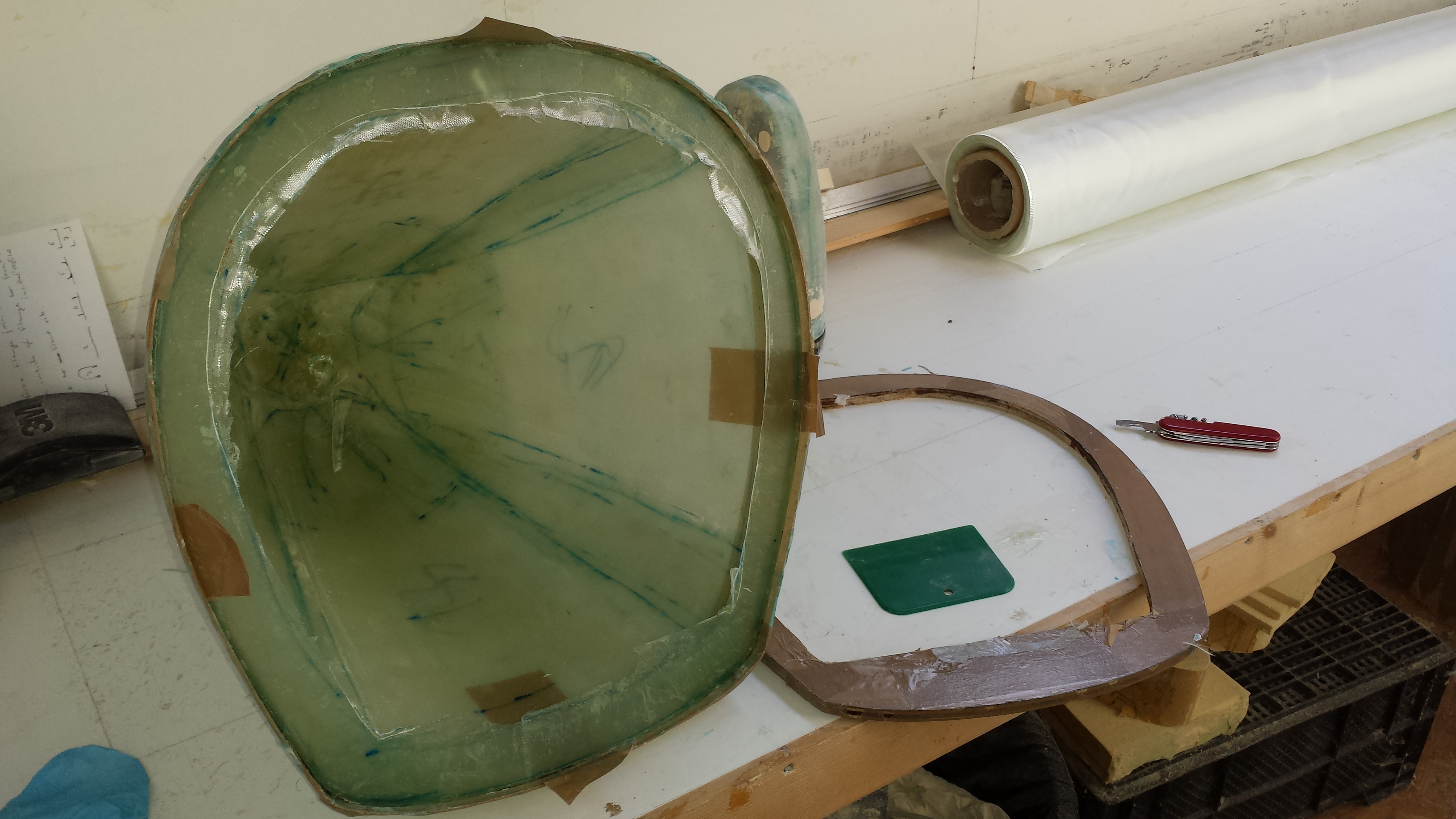
Nose (& Tail) Cone
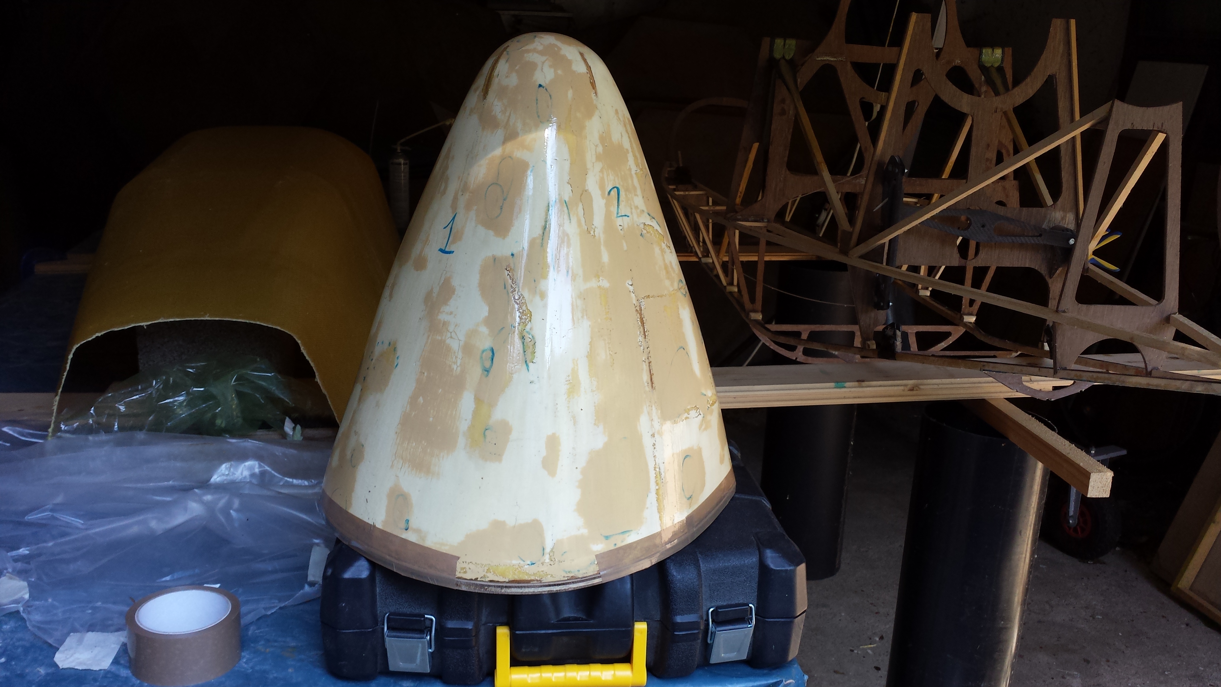
Although I don't seem to have any photos of how I shaped my nose cone plug, I fabricated a male plug from a 1/2" thick plywood base board with the same profile as the first pod frame at Station 0.00" and two interlocking 1/8" thick plywood forms, derived from the plan view and side elevation on the plans. The four spaces, or quartiles between the 1/8" plywood forms were filled in with blocks of polystyrene insulation board, which was then rough shaped using a hand saw, rasp and various other abrasive weapons before sanding to its final shape.
Once I was happy with the shape of the polystyrene plug, I painted it with several coats of varnish to protect it from being dissolved by the next layer of polyester car body filler.
Once the varnish layers were dry, I applied several thin layers of polyester based car body filler, making sure to fill in any voids in the polystyrene foam. Each layer of car body filler was sanded down, and the process was repeated until I achieved a (more or less) symmetric, pleasing shape and super smooth surface.
The super-smooth, fine sanded polyester surface then received several coats of mould parting wax, buffed to a shine between coats, followed by a coat of PVA mould parting liquid.
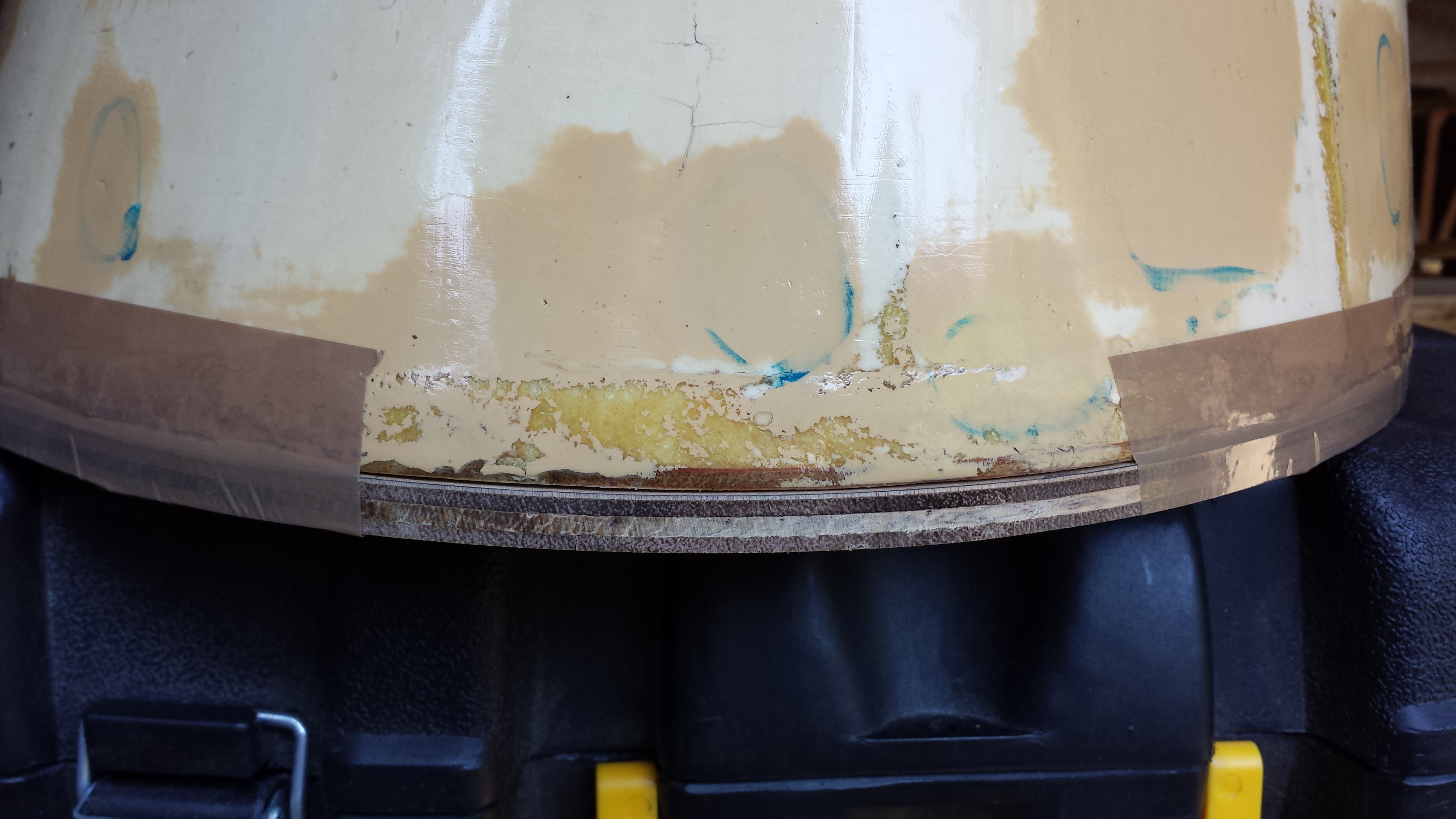
The bottom edge of the plug was extended with a piece of 1/2" plywood, which allows the final mould to be trimmed back to remove any bridging that might result in the next step.
Next, the plug was hot glued down to a piece of 3/4" thick melamine covered chipboard, covered in brown packing tape. Polyester resin doesn't stick to the tape, so no wax or PVA is needed.
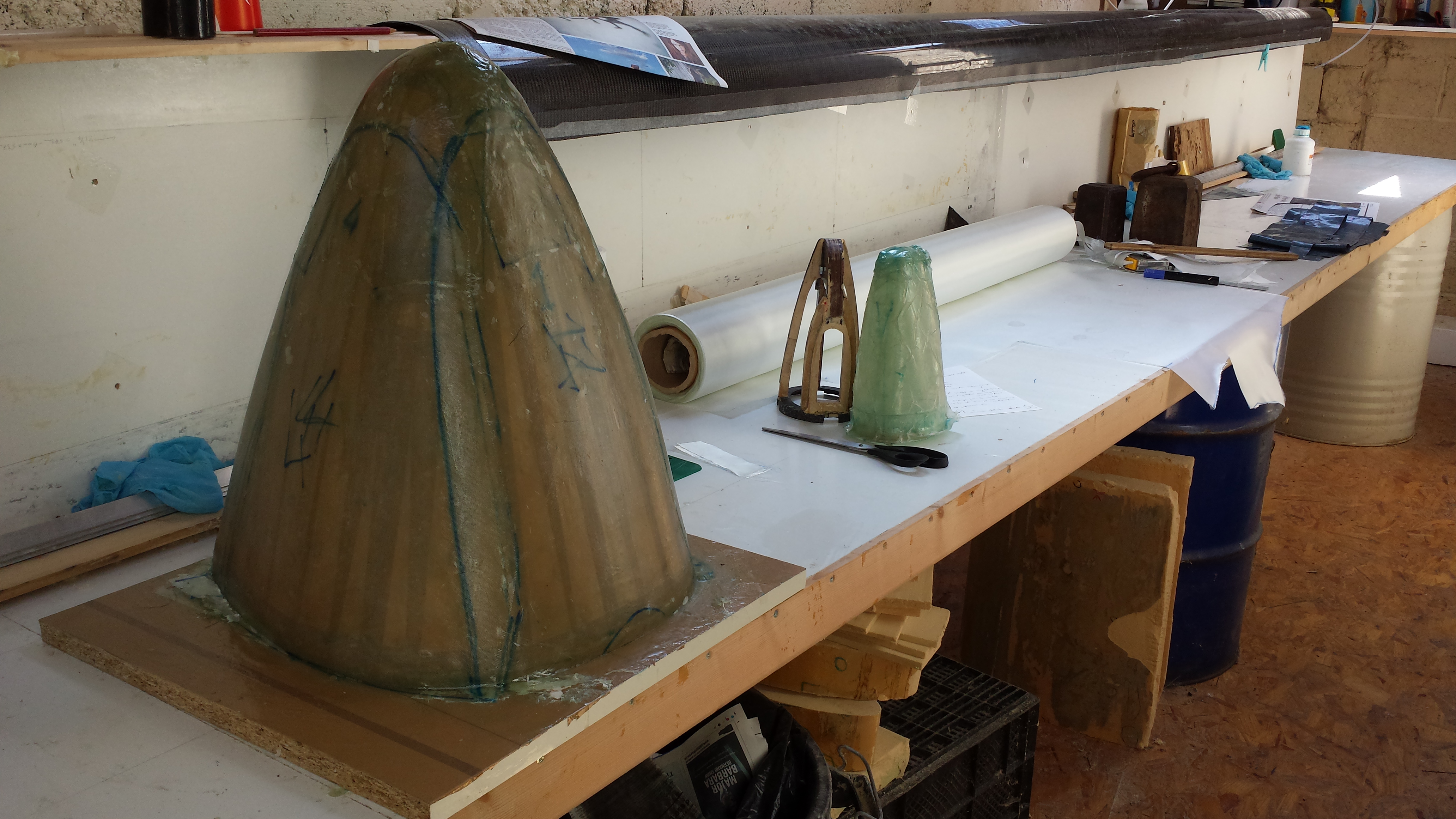
The plug was covered in three layers of chopped strand mat glass fibre cut into easy-to-handle panels. The edges of each panel of chopped strand mat were cut so that there was a 1" - 2" overlap. The point of the nose also received two or three circular panels to fill in any gaps. You can see the individual panels of glass mat in the photo below. Polyester resin was used for this stage of the mould production.
Once the polyester resin was fully cured, the mould was removed from its melamine base board and the plug was gouged out with a variety of tools to leave a super-smooth inner surface. The bottom edge of the mould was trimmed back to its final size, removing any trace of bridging between the plug and its melamine chipboard base.
The next step was to cut out a 1/4" thick plywood insert, copied directly off the pod frame at Station 0.00" using a router and a trim bit. The inner surface of the plywood was covered in brown packing tape. This forms a base for a flange to be laid up in the next step,
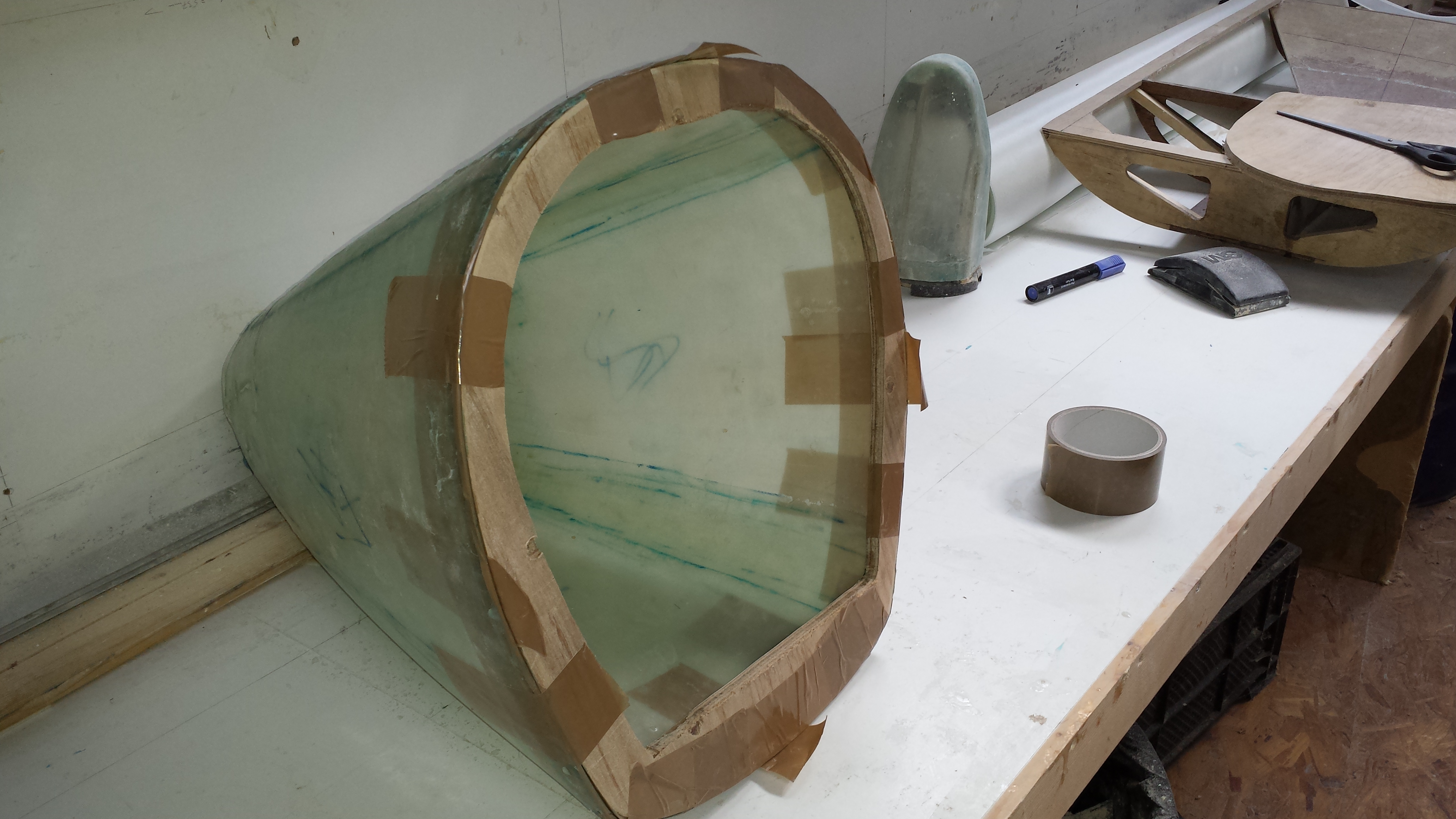
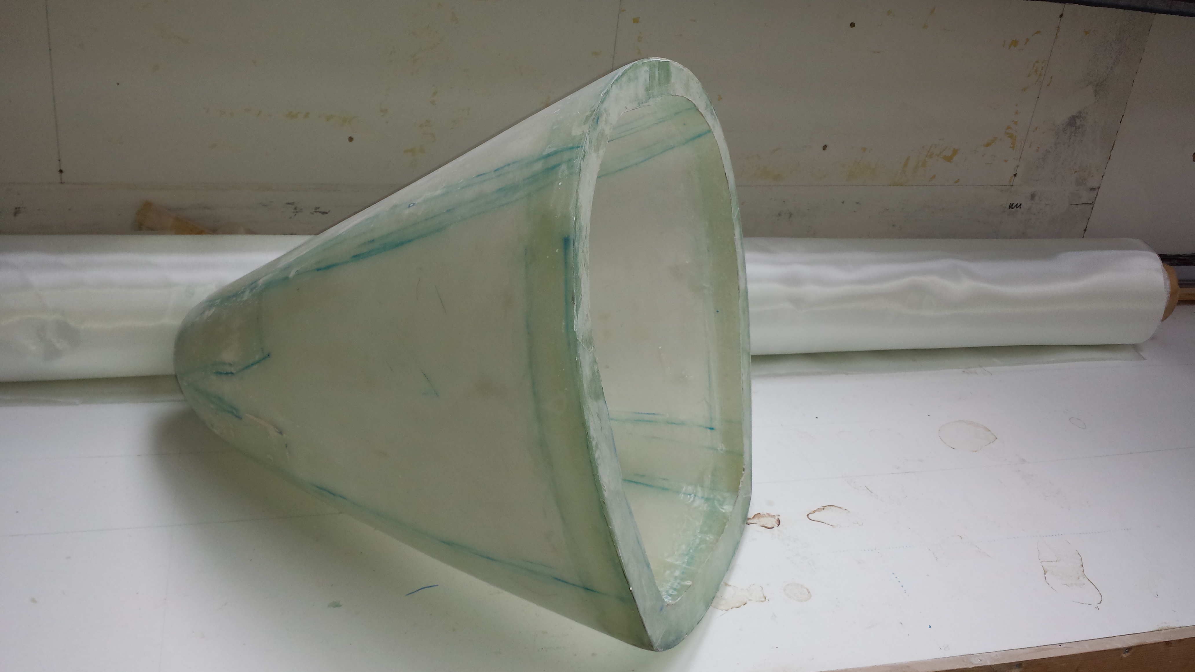
Using the same pattern templates as were used to cut out the chopped strand mat, panels of 200gsm (or possibly 280gsm - I can't remember!) plain weave S-Glass were cut out and wet laid into the mould using a slow cure epoxy resin. I think I used two layers of S-Glass in my nose cone, with a third layer on the tip of the nose for added strength. The area around the flange also received a third layer of S-Glass for added strength.
Once fully cured, the S-Glass flange was trimmed back and neatened up, and the 1/4" plywood flange base was removed.
A certain amount of effort was needed to remove the thin nose cone from its mould without damaging it, but I eventually found that using an air compressor and air gun to blast high-pressure air in between the mould and the nose cone inside it, broke the seal quite effectively.
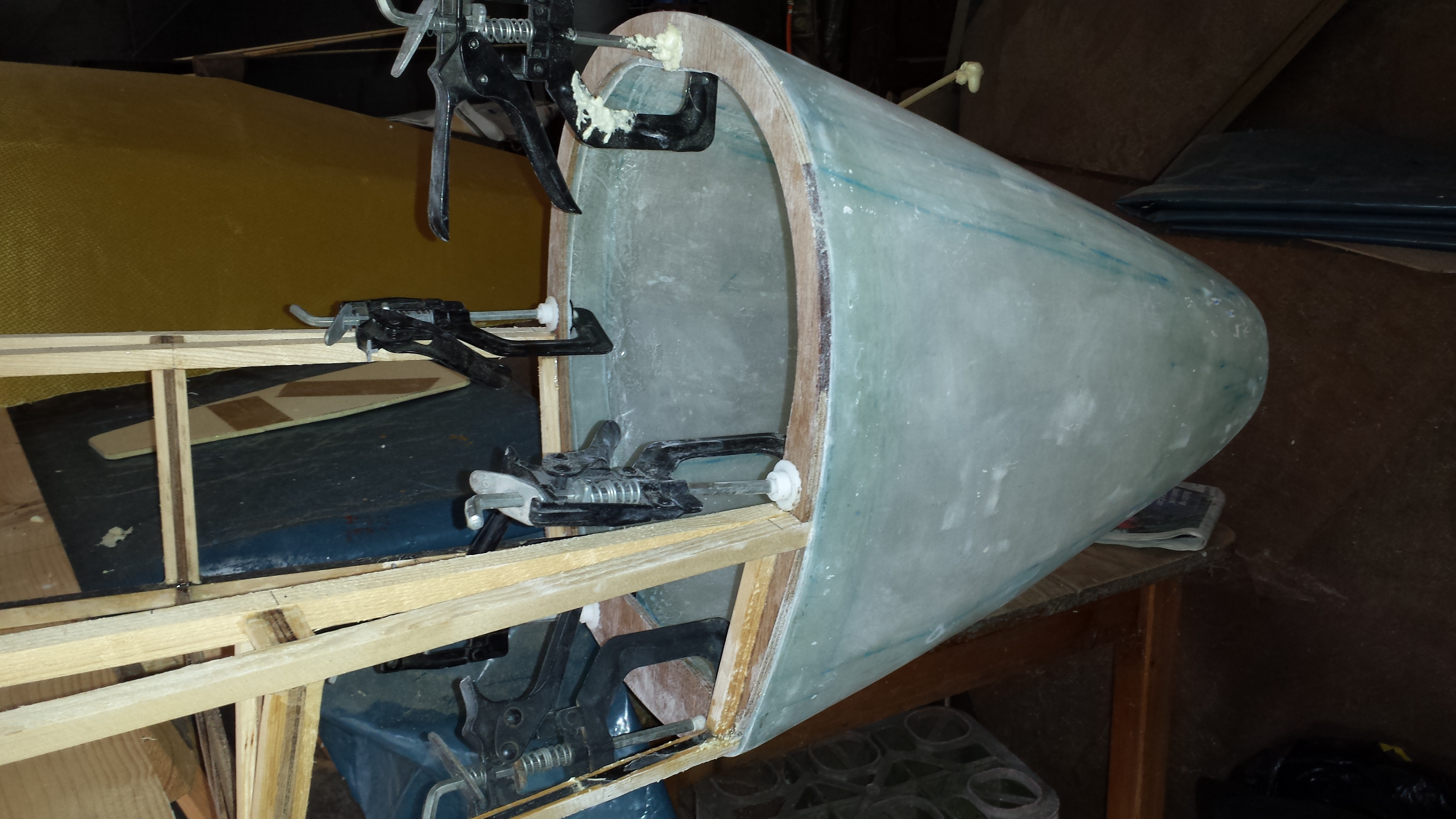
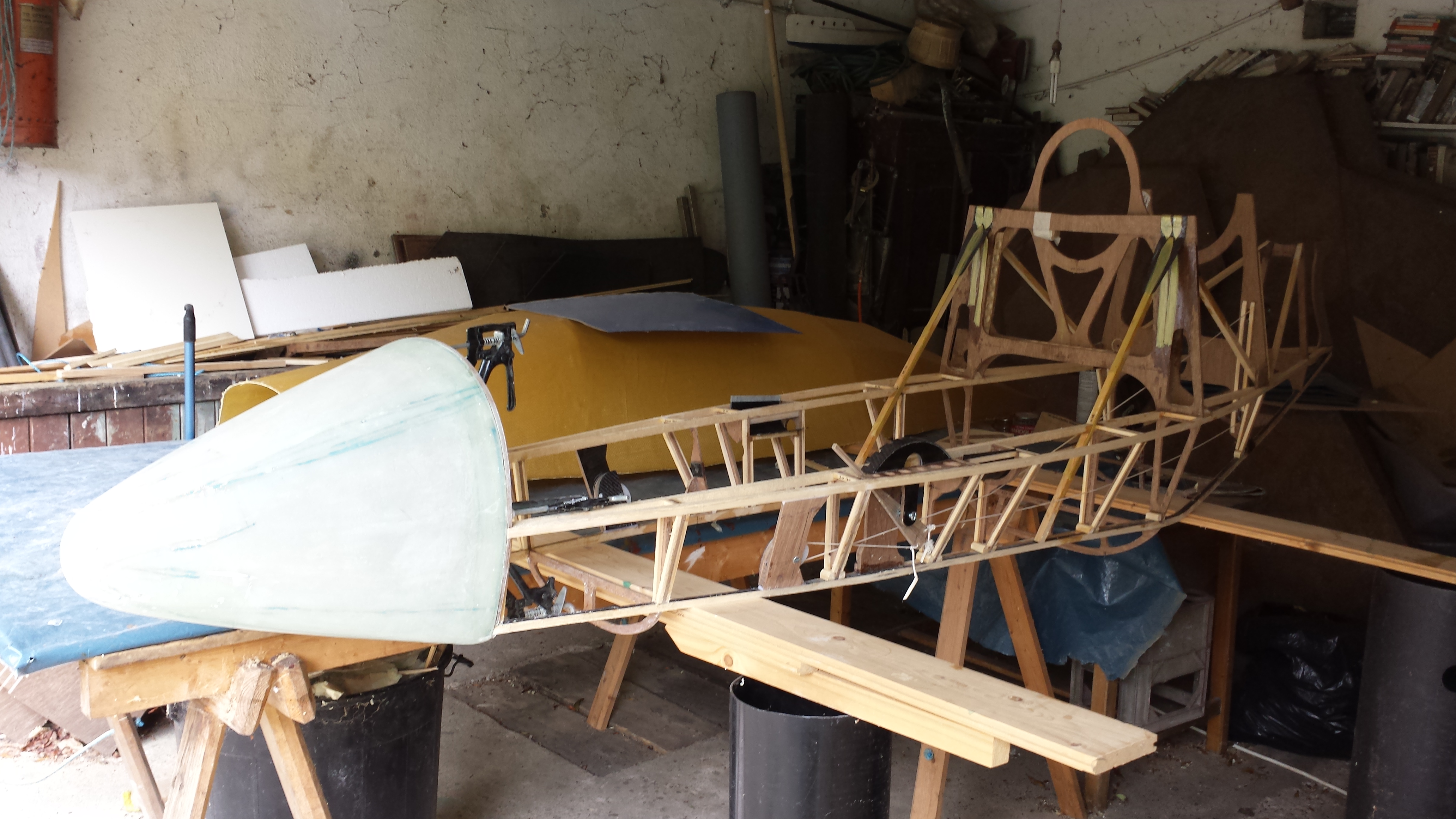
The finished nose cone then just needs to be washed to remove all trace of the PVA parting compound before bonding it on to the pod.
The eagle eyed may have noticed that my nose cone is a lot more pointy than in the plans! :-)
Job done!
Wings
Coming soon...
Air Brakes
Coming soon...
Covering the Flight Surfaces
2nd March 2018 - This page is under construction...
Covering the Flight Surfaces
I looked at a number of different covering systems and after comparing the pros and cons of each, the one that stood out far and above all the others was Oracover UL600 from Lanitz Aviation in Germany... unfortunately it was also the most expensive at the time I needed it, which coincided with me being broke! So, with regret, I had to opt for a cheaper, more labour intensive and heavier solution.
EkoBond - a water based, heat activated cement for bonding the fabric to the airframe
EkoFill - a water based fabric filler, which also doubles as a UV protection layer
EkoPoly - a water based 2-part catalysed polymer top coat (in a range of colours)
Digitally calibrated Iron for activating the EkoBond and also for heat shrinking the fabric.
The entire order, including shipping from the USA to Ireland came to around €1700.
The Stewart Systems products are all water based and are solvent free, making them a pleasure to use! There is a comprehensive workshop manual for working with all their Eko- products, which goes into great detail. The bones of it, however, can be summarised as follows:
Measure and cut out the fabric for all your parts that need covering
Clean your airframe surfaces with EkoClean
Scuff up the sirframe surfaces where the fabric will be bonded to it
Clean each piece of your airframe with EkoClean again!
Apply EkoBond to the airframe where the fabric will be bonded to it and allow to dry (~20mins)
Drape the fabric over the airframe and press it down gently into the EkoBond
Carefully lift, stretch and re-press the fabric back into the EkoBond with a stiff felt spatula (synthetic felt furniture glides work well!) This allows you to remove any wrinkles from the fabric and pre-stretch it.
Use the hot iron to press the fabric into the EkoBond and activate the glue for a permenent bond
Calibrate the iron and use it to heat-shrink the polyester fabric incrementally at 200F, 250F and 300F.
Clean the polyester fabric with EkoClean to remove any hand grease and dirt
Rince the polyester fabric with clean water to remove all trace of the EkoClean and to dampen the fabric prior to applying the EkoFill
Apply one (or more if necessary) cross-coat of EkoFill using a foam brush and wait for it to fully dry (~3hrs)
Very lightly sand the Ekofill to remove any unevenness in the surface and wipe down with clean water
Spray one (or more if necessary) coat of EkoFill and allow to dry fullt.
Very lightly sand the Ekofill to remove any unevenness in the surface and wipe down with clean water
Spray as many coats of EkoPoly as necessary to build up a solid glossy finish.
Easy-peasy - and not as scary as many people on YouTube like to make out!
Take a look at my Construction Photos - Wing Covering pics for more details.
Use Oracover 600UL if you can afford it - it involves significantly less work and will give you a much better and lighter surface. And, because the warp and weft are designed to shrink different amounts, you will end up with far less 'scolloping' between the ribs aft of the main wing spar. That said, I'm very happy with the results I got with Stewatr Systems.
Take care not to over-shrink your fabric, as it is possible to deform the airframe... as I found out!
Painting the Wings
Coming soon...
Load Testing the Wings
Load Testing the Wings
The video, below, shows not one, but two wing load tests. During the first load test the spar cap under compression buckles and fails catastrophically because, although there is more than enough carbon to carry the loads if the carbon fibers remain absolutely straight, the spar is dimensionally too thin' to 'prevent it from deforming. Once it started bending... it was doooomed!
It should be noted that my 3-part wing is a radical departure from the published plans, and the failure mode shown in the video should not suggest any deficiency in the original plans... but in my execution of them! In the original plans, the 2-part wing is joined at the wing root by a number of broad metal plates, which serve to stiffen the spar at this point and prevent it from buckling under compression.
The 'failed' load test was actually 100% successful in that it exposed both the weakness in my design and a gap in my knowledge and understanding of how loads and forces work in beams!
Load Testing the Wings to their 5g Design Limit Load
I have added a new page to my spreadsheet detailing my Wing Load Test calculations, which you can download here: Phil's Carbon Dragon Spreadsheet
Click >>>here<<< to view the forum discussion following the first load test and to see how I repaired the damaged spar.
The following quantities need to be known in order to calculate the test load and distribution:
The 1g Normal Operating Load - This is the weight of EVERYTHING that goes up in the air (glider + parachute + oxygen system + radios + instruments + pilot + ham sandwiches + pilot's preferred in-flight refreshing beverage) LESS the weight of the wings, which are deemed to carry their own weight.
The 5g Design Limit Load (Load Factor) - This is the 1g Normal Operating Load x 5. This is the load the wings must support under test conditions with no failure or permenent deformation.
Note: the Ultimate Load Limit is the Design Limit load x 1.5 = 7.5g in this case. This is the load at which the wings are expected to fail catastrophically. Unlike wings fabricated out of aluminium, which yield first elastically, and then non-elastically before failing, carbon fiber wings do not yield non-elastically before failing. Carbon fiber wings will carry the increasing loads applied to them and will yield elastically right up to the point of catastrophic failure. Then they snap!
The Total Load per Wing - This is half the Design Limit Load, as the load is spread out over both of the two wings.
The Total Wing Area - The area of a standard, unmodified Carbon Dragon main wing is 153.34sq-ft
The Test Load (per Square Foot of Wing Area) - This is the Normal Operating Load x the Load Factor / the Total Wing Area
In my case this gives me the following numbers:
Gross weight of glider (including the wings, parachute, pilot and ham sandwich): 145kg Weight of the Main Wings: 39.7kg
Thus our 1g Normal Operating Load = 145kg - 39.7kg = 105.3kg 5g Design Limit Load = 105.3 x 5 = 526.5kg Total Wing Area = 153.34sq-ft Test Load = 526.5kg / 153.34sq-ft = 3.43kg/sq-ft
Next we need the surface area of the wing between each pair of wing ribs. Multiplying the area between each pair of wing ribs by the Test Load (3.43kg/sq-ft) gives us the load we need to apply to each section of wing. These area numbers can be directly lifted out of my spreadsheet and applied as follows:
NB: Please forgive my mixing my units (area in sq-ft and load in kg... although I'm a pounds, shillings and inches kind of guy, but I found it easier and more accurate to weigh my bags of sand in kg! :-)
The wing is assembled and suspended upside down from the four pilot pod attachment points, making sure that the wing is level, span-wise using a digital clinometer or a spirit level. The aft support bar, attached to the aft wing attachment points (see photos and video) is suspended from two M10 threaded rods. These rods are then adjusted until the leading edge of the wing is tilting downwards by around 10° to simulate a pitch-up maneuver (see Structural Proof Testing by Stan Hallfor an explanation of why.) The 10° pitch angle can be verified by placing the clinometer on a flat surface, zeroing it and then placing it against the flat shear web of the spar at the center of the wing.
Next, two car jacks, fully extended, are placed under the wing tips with a little padding to protect the wing from the metal jack. Care is taken to ensure that the jack(with padding) just contacts the wing directly under the end of the wing spar. The wings are covered in thin sheet plastic and old bed sheets to protect the wing skins from dirt and damage before the bags of sand are placed gently and symmetrically onto the wing's D-section (approximately between each pair of ribs) from either end, and ending up at the wing root.
The car jacks are now lowered slowly and evenly, frequently checking that the deflection at both wing tips is the same. If the car jacks don't both have exactly the same thread pitch, then one jack will lower at a faster rate than the other, and compensation needs to be made for that every now and then.
As the jacks are lowered, the lower surface of the D-section comes under increasing compressive load and it will visibly begin to deform or buckle like a dent in an oil drum - this is the 'oil-canning' referred to in the video. This is normal and expected, and the creases and deformation will disappear once the load is removed. They do not damage the D-section... unless of course something goes south on you!
The car jacks, fully extended at the start of the load test and just touching the underside of the unloaded wings were measured and noted to be 15" high. Once the wings were fully laden with the sand bags and the jacks were fully lowered so that they were no longer supporting the wing tips, the height of the jacks was measured again and noted to be a shade over 5". Thus the wing tips deflected downwards by just under 10" at the full 5g loading - slightly less than expected!
Once both car jacks are fully retracted and are not carrying any weight from the wing tips, the test is complete and the sand bags may be removed very carefully (and symmetrically) from the wing tips in towards the wing root. If the wings survive the load test then you have a glider!
Trailer Fabrication
4th March 2018 - This page is under construction...
3rd March 2018 - This article is under construction!
Bungee Launch System
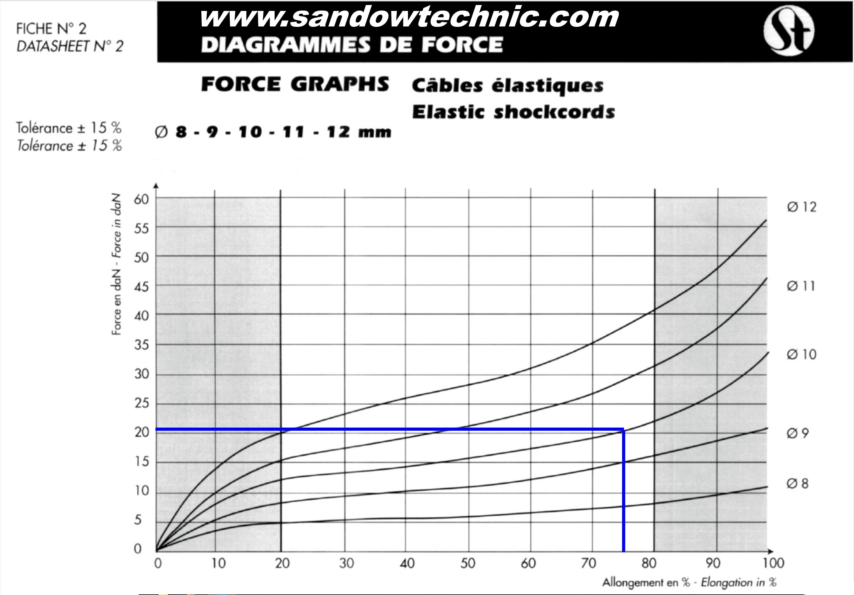
After coming close to disaster during a light-wind foot launch in his Swift Light, and having seen Jac Bott's bungee launch system first hand in action in France, my friend, Ken Hickey wisely decided not to attempt any further foot launches and to build a bungee system for both his Swift and my Carbon Dragon, and we agreed to share the expense 50:50. After a little research and a crash course in Hook's Law of Springs and Elastic Potential Energy, Ken came across a company called Sandow Technic in Germany who offer a range of bungee ropes suited to our application. When compared to other manufacturers data sheets, the Sandow Technic bungee ropes pack more potential energy into their ropes than any of the other offerings.
Our system originally comprised 6 x 17m lengths of 10mm diameter bungee ropes, but after our initial tests (see video below) we doubled the length of our ropes to 34m to increase the potential energy in our system for a given amount of stretch. Each 10mm diameter rope yields approximately 22daN (or 22Kg) of force when stretched 75% beyond its slack length (i.e. 17m x 1.75 = 30m.) Multiply that by six ropes and the total force yielded by the system becomes 6 x 22daN = 132daN (or 132Kg.) It is important to understand that doubling the length of the bungee ropes does not double the force yielded (assuming a similar, 75% stretch, now 60m) but it does increase the potential energy in the system and allows the bungees to deliver that force for a longer time, and thus impart that extra energy to the glider - longer ropes put a bigger WOO! in your WooHoo! as you launch! :-)
[Insert photos of individual components here...]
Bungee Launch System Test - for Swift and Carbon Dragon!
Ken Hickey's 1st Swift Light Bungee Launch in Ireland 26 Jan 2018
When comparing the force graphs for the various diameter bungee ropes, you may wonder why we didn't opt for the 11mm, 12mm or any of the thicker ropes that are available. Just remember that one person must be able to stretch each of the six ropes, unassisted if necessary. This is only just possible with the 10mm rope, which at 75% stretch is almost capable of launching me into outer space if I loose my balance or slip! A single bungee rope is frighteningly strong!! I definitely would not like to have to try stretching the 11mm rope on my own.
Construction Videos
June 2018 - It flies! Bungee launch at the Curragh, Co. Kildare, Ireland.
Playlist - Play all the Carbon Dragon videos in sequence
- Setting up parts for Vacuum Assisted Resin Infusion
- Vacuum Assisted Resin Infusion
- Debagging first batch of ribs
- Demoulding a part
- Fabricating Foam Cores
- Shaping the Leading Edge Moulds
- Covering the Leading Edge Foam Plug in Fiberglass
- Shaping the Outer Leading Edge Foam Plug
- Infusing the Tail Boom Skins
- Rib Trimming
- Infusing the Horizontal Stabiliser Skin
- Trimming the Horizontal Stabiliser Front Spar
- Bonding the Tail Boom Halves Together
- Laying the up Main Wing Spar center section
- Schempp Hirth Air Brake Prototype
- Fabricating Flaperon Ribs - Start to Finish
- Truing up the Wing Rib Cap Strips
- Load Testing the Wings to their 5g Design Limit Load
- Spray Painting the Wings
- Bungee Launch System Test
- Trailer Fabrication
- Covering the Wings
- June 2018 - Flight Testing at the Curragh, Co. Kildare, Ireland.
Errors in the Plans
8mm Ply
Throughout the drawings you will see reference to '8mm ply'. This should read '0.8mm or 1/32" Ply'.
This very thin plywood is used for all the leading edges, spar webs and rib gussets.
Rudder
One of the dimensions of the rudder spar on drawing #4 is incorrect.
Drawing #4 shows the width of the top end of the spar to be 2 1/8", which is too wide.
It should read 1 3/4".
All the other dimensions on the drawing are correct.
SOLUTION: Make the rudder spar with a top end width of 1 3/4" rather than 2 1/8". Everything then fits!
I discovered this error while assembling my rudder (gluing the hinges, hinge supports, D-section formers, etc.) to the rudder spar. The triangular ribs are are not the same width as the spar where they are supposed to be bonded to it.
I double checked my spar and its physical dimensions are exactly as specified in the plans. The ribs were made using the plans as a template and my ribs match the plans with better than 1mm accuracy but I was at a loss as to why there is a growing disparity in the with of the ribs as you go up the spar:
Rib #6 was particularly bad - the spar is 54mm (2 1/8") wide at the top but the width of the rib where it joins the spar is 44.5mm (1 3/4") - there's no way this was a scaling error on my printed plans! I checked the scale of my drawings and it was close enough to the correct scale that this did not account for the error. What was I missing???
I emailed Rick Mullins who responded immediatly with the (now!) obvious answer:
Rick replied: "Yeah, you've discovered one of the many errors in the plans. The drawings show the overall width [at the top of the rudder spar] as 2 1/8" and the space between the rib stringers as being 1 1/4". However the rib stringers are made of 1/4" spruce and 1 1/4" + 1/4" + 1/4" = 1 3/4. I made notes in my plans when I found errors but missed marking this one."
Control Stick Assembly
Following on from the error on drawing #4 of the rudder spar top end, Rick Mullins highlights a few more errors he found the hard way:
Yeah there were a few parts I remade because I didn't catch the errors soon enough.
When you get to the control stick and pivot assembly on sheet 20 you'll see he must have been having a bad day. I made those pieces and welded them wrong 2 times before I caught it.
The left drawing of the pivot plate shows the head of the bolt and the flat side to the left. All the other drawings show the shaft side of the pivot plate with the flat side still on the left.
If you are looking at the pivot plate on the bolt head side, the flat side should be to the right, the left drawing is wrong.
Also the control stick is made of 5/8" steel so the hole in the primary arm should be 5/8", not 3/4" as shown in the plans.
H-Stab & Elevator Hinges
The other big error that Rick Mullins encountered during his build is to be found on drawings #5 and #6 of the Horozontal Stabiliser and Elevator. On the drawing of the Horozontal Stabiliser the hinges are mounted aligned with the ribs and D-section formers, but are shown significantly offset on the drawing of the Elevator - they don't line up! You will need to make sure that you mount the male side of the hinges (the side with the tapered pins) are correctly aligned to mate with their female counterparts. You will also need to make the appropriate cut-outs in the bases of the D-section formers to allow the base / flange of the male hinge to be bonded under the formers. The formers can be bonded into the centre slot of the male hinge with the tapered pin passing through the D-former.
Rudder Hinges
The two halves of the middle rudder hinge do not lign up on drawing #2. The male half of the hinge is shown incorrectly positioned on the drawing of the rudder but shown correctly in the drawing of the rudder spar just next to it. This is easily caught as the male halves are bonded to the rudder spar with the hinge pins inserted into the female halves already bonded to the tail fin rear spar to ensure perfect alignment.
Tail Fin Front Spar
Drawing #3 shows an incorrect dimension for the lower end of the vertical tail fin front spar web. The half-width of the spar web is correctly shown as 2.41" but the full width is incorrectly shown as 2.82". It should read 4.82".
Note also that the spar caps extend beyond the bottom of the spar web. The spar web is 50.07" long but the spar caps need to be 58 13/16" (58.8125") to reach down the sides of the tail boom as they taper off. This is important to note if you are laying up this spar using composites and carbon rod for the spar caps - don't leave yourself short (like I did!) Also, the reinforcement plate at the bottom of this spar can be incorporated into the spar during lay-up. I pre-fabricated my reinforcement plate out of 5mm foam board with seven layers of carbon cloth either side.
Elevator Rib 1
Thanks to Bertrand Botrel for spotting this one!
The dimension shown of Rib #1 on Drawing #6 is incorrect. It should read 11.5" (not 10.75")
Thankfully the drawing itself is correct and may be used as a template.
Horizontal Stabiliser Front Spar
Drawing #5 shows two incorrect dimensions for the widest point on the front spar of the horizontal stabiliser. The drawing of the front spar gives the widest point (at Rib #1) as 4.50", which does not match the dimension of Rib #1 where it is bonded to the spar. Direct measurement of Rib #1 (which is drawn full scale on Drawing #5) reveals that the correct dimension of the spar at this point should be 3 13/16ths". The half-width dimension is also incorrect and should read 1.91" rather than 2.25".
Elevator Cable Pulley Brackets
I should have spotted this much earlier, but on Drawing #21, the two Elevator Pulley Brackets are shown mounted upside down. Made to the plans (as I did!) the two elevator cables are able to fall off the pulleys when the cables are slack or loose. This is not a problem as long as the cables are kept under tension, but they must be double checked if you detach the cables for any reason.
The carbon brackets that envelope the pulleys should be mounted the other way up, in such a way as to prevent this problem.
Pilot Pod Template 54.50"
Pod Frame Template at 54.50" - the centre line is drawn incorrectly. When the 1/2 template is flipped over on its given centre line, an incorrect part is obtained. The inside bottom of frame-to-centre-line distance should be 8.5" for a 17" wide cockpit width.
Modifications
3-Part Wing
Description
Designing a Three Part Wing
The original Carbon Dragon, as designed by Jim Maupin, had a two-part wing joined at their root, at the centre-line of the glider. With a full wingspan of 44 feet, this means that any trailer built to haul the glider around would have to accommodate two 22 foot long wings - not only unwieldy for a single person to handle and assemble (especially in a breeze) but also likely to incur extra charges every time the glider is taken by ferry to the continent from Ireland. Splitting the wing into three sections would reduce the longest component to around 15 feet.
A number of issues arise when considering a three-part wing:
Where to split the wing:
If we split the wingspan roughly in three, each section will be 14.66 feet (or 176 inches) long. It makes sense to split the wing just outboard of the nearest rib. So if our centre section of wing is approximately 176 inches long, dividing this dimension by 2 (half, either side of the centre line of the glider) we get 88 inches. Looking at the drawings, Rib #5 is closest to 88 inches outboard of the root, 94 inches out from the centre-line. The total length of the centre section of wing is therefore 94 x 2 = 188 inches or 15.67 feet long. The length of the two outer sections of wing then become 44 feet less 15.67 feet = 28.33 feet divided by 2 = 14.165 feet or 169.98 inches long.
Dihedral:
Dihedral must be built into the centre section of the wing if we are to maintain the inherent stability of the design. We can work out the amount of dihedral by carefully examining and measuring the drawings.
On Drawing #1 we see that the wingspan of the glider is 44 feet, so one wing length, root to tip is 22 feet or 264 inches.
Drawing a line perpendicular to the vertical centre-line of the glider, from the vertical midpoint of the spar-web at the root out to the vertical midpoint of the spar-web at the wing tip, we can measure how much higher (dihedral) the centre-line of the wing tip is above the centre-line of the wing root. I measure this as 12/64ths (or possibly 13/64ths) of an inch... approximately!
Ignoring the scale given on the drawing (because the printout of the drawing from the PDF file cannot be trusted) we can derive the true scale by dividing the wingspan dimension indicated on the drawing (44 feet or 528 inches) by the physical measurment of the drawing of the same dimension (16.75 inches). Thus the true scale of the printed out PDF drawing is 528 / 16.75 = 31.522x.
Multiplying our 12/64ths of an inch by the correct scale, 31.522, gives us the slightly odd dimension of 5.9 inches. Given the thickness of the lines on the drawings, it is difficult to get an exactly accurate measurement, and we could easily be out by more than 1/64 of an inch, and indeed Steve Adkins reckoned it to be 6 inches exactly, which seems not unreasonable.
Steve Adkins notes: "As to the dihedral: dihedral is provided by building the lower spar cap 0.25 inches longer than the top spar cap. The assembly pins are 11 and 5/64th inches apart at the bolt centers. From this, you can calculate how much a wing tip would be raised. I am thinking the center line of the wing tip would be raised nearly 6 inches above the wing root center. One builder mentioned to me he was going to build a flat wing which I discouraged (I wouldn't second guess Irv Culver)."
With this new dimension quantifying the dihedral built into the wing (how much higher the centre of the wing tip is to the centre of the wing root) we can, by simple trigonometry, work out the angle at which the wings tilt up from the vertical centre-line of the glider. This angle is 1.3°. It is critical to know this angle when it comes to laying out and fabricating the centre section of a three part wing.
Spar Cap Root Junctions:
Attention need to be paid to how we treat the stresses on the upper and lower spar caps where they come together at the root. The pultruded carbon rods used in the spar caps will not bend at the root / centre line to accommodate the 2.6° (2 x 1.3°) of dihedral built into the centre section of the wing. [NB: actually the rods *will* bend to accommodate the built-in dihedral, as I later discovered, but an unbroken bundle of rods does make the lay-up and bagging process a bit trickier] The bundles of rods must therefore terminate at the centreline and a load transfer bar must be designed and incorporated.
In designing the load transfer bars which transfer the spar cap loads from the carbon rods to the wing root metal fittings for a two-part wing we calculated that the bar must have a minimum thickness of 0.184". The 284 Twill Carbon Fibre cloth I am using has a thickness of 0.011" per laminate, so therefore we need a minimum of 0.184 / 0.011 = 17 layers of cloth in our load transfer bars (for both upper and lower spar caps) spanning the space between the two root ribs.
It would do no harm (and add little weight) to beef up the centre section of the spar web, between the two root ribs, to make the whole assembly a little more robust. One way to do this is to sandwich a plate of 5mm thick PVC foam board between the root ribs and the upper and lower spar cap load transfer bars. As luck would have it, 0.184" = 4.67mm thick, so by adding just one more laminate of carbon cloth to our load transfer bars (making them 18 laminates thick) will allow us to create a perfectly flush surface between the root ribs and the spar caps of the centre section!
Note: When the centre section of the three-part wing is not connected to the rest of the glider (i.e. during rigging / de-rigging and transport) the root section of the spar will be liable to experience large bending forces if it is not properly braced and supported at the drag spar connection points, and there is a very real possibility of damaging the spar. Inserting a short beam of plywood between the drag spar connection fittings will prevent the spar from bending in the wrong direction.
Wing connections:
Splitting the wing at a rib position allows us to close off the ends of the centre section of the wing by incorporating a blanking plate into the rib to prevent dirt and insects from getting in. By replicating this rib (Rib #5) we can also close off the outer sections of wing also and provide a solid mating surface to the two parts of the wing. As we will see below, the wing connection fittings and load transfer bars will need to protrude through all of these wing section end ribs.
While we can safely use the 17 layer (minimum) load transfer bar to transfer the loads from the spar caps across the root section of the wing, the loads on the wing spar caps and shear web are considerably less when we move outboard along the wing. At Rib #5, where we plan to split the wing, the loads are considerably reduced (less than half) from those experienced at the root. It is sensible, therefore, to recalculate and redesign the load transfer bars and the metal wing connection fittings so that weight can be saved where possible.
Redesign the connection fittings and method...
(to be continued...)
Flaperons:
Joining the sections of flaperon - maintaining stiffness!
THIS ARTICLE IS INCOMPLETE - check back later... possibly much later!
I am investigating the possibility of replacing the single delta shaped spoiler, behind the pilot's head, with proper Schempp-Hirth air brakes inside the wings, just inboard of Rib #5, and just outboard of the H-Stab to elimenate any interference (by turbulated air) with the rudder and elevator. I have a basic design concept on paper but it has yet to be prototyped and load tested up to and beyond Vne by attaching it to the roof rack of my car and driving it up and down the motorway! I will need to construct a small section of wing (leading edge, wing spar and trailing edge...) between Ribs #4 and #5, where the air braek will be fitted, so that both the air braek and the wing section (against which the braek forces will react) can be tested to see how they perform.
Although this type of air brake will probably add a little weight to the glider overall, I want my Carbon Dragon to have a cockpit layout that will be familliar to any sailplane pilot. I also believe that the new Schempp-Hirth brakes will be easier to use with greater finess. Some pilots report the original delta shaped spoiler is difficult to open fully at higher airspeeds. Maintaining a constant glide slope requires accurate and fine adjustment of the air brakes - something not possible with the original delta spoiler.
(Details coming soon...!)
Tail Boom
I am making the tail boom removable from the pilot pod - this requires a new attachment method using high shear strength pip pins.
I am making the tail/rudder removable from the tail boom for more compact transport - this requires a new attachment method using high shear strength pip pins.
Both of these changes will also require modification of the control wire system for the rudder and elevator.
Details coming soon...
Materials & Suppliers
Materials Used
Materials & Suppliers
This list was updated 07 April 2019
https://www.easycomposites.co.uk Epoxy Infusion Resin + SLOW hardener - low oder (my recommendation) Composite and Vacuum bagging supplies Carbon / Aramid (Kevlar) / Glass fibre / Core materials etc. Carbon tubing etc.
https://www.r-g.de/en/home.html Different Epoxy systems (including 5 minute for small bonding jobs) Connto Flock / Micro Baloons Composite and Vacuum bagging supplies Carbon / Aramid (Kevlar) / Glass fibre / Core materials etc. Carbon tubing etc.
I used 3k 195-200gsm Carbon Twill weave cloth for throughout the project, and a layer of 170gsm plain weave Kevlar cloth in the leading edges.
1/2" Medium Density Fiberboard (MDF) - for fabricating the moulds for the foam cored, carbon fiber wrapped ribs and parts
Ronseal Diamond Coat Polyeurathane Floor Varnish - for sealing the MDF moulds
Double-Sided Sticky Tape - used in the preparation of the PVC foam core blanks
Closed Cell PVC Foam Board (1m x 1m sheets - 5mm and 10mm thick) - used to create the foam cores of all the ribs and parts. All the ribs and other parts of the wings and control surfaces (except the flaperons) are made using 5mm thick foam cores. The flaperons must be 8mm thick and are fabricated out of 10mm thick foam board, shaved down to 8mm in order to preserve the geometry of the flaperon ribs which are bonded to each other at 90degrees along the length of the flaperon. If the flaperon ribs were fabricated out of 5mm foam then the geometry would not be preserved.
Carbon Fiber Twill Cloth (non-cosmetic grade is significantly cheaper than the cosmetic grade, and has exactly the same strength. The non-cosmetic grade cloth simply has coloured threads woven into it at regular intervals to aid in alignment and cutting.)
Workshop fit-out: ----------------- Work table - 22' x 2' Melamine = 2 sheets of 8' x 4' or 3 lengths of 8' x 2' 3 x 600mm x 8' lengths of edged melamine 3 x 16' lengths of 3" x 1" deal to support edges
Materials & Consumables: ------------------------ Carbon Fiber cloth Carbon Rod Carbon Roving Epoxy system - resin + hardner - https://www.aircraftspruce.com/catalog/cmpages/aeropoxy.php PVC Foam core sheet 8 sheets of 8' x 4' x 0.5mm Veneer: Supplier: TP Veneers 839 5244 - Baldoyle Ind Est (just around the corner from Abbey Woods - www.abbeywoods.ie) Price: €1.50 - €5/sqm (1 sheet of 8' x 4' = 32sq-feet = 2.973sqm = €4.46 - €14.87 per sheet) (also available in 7' x 3' sheets)
Consider using Moyes Matrix leg-loop fastners for the pilot's harness webbing. http://www.moyes.com.au/
Consider replacing the bomb-bay doors with overlapping stretch-neoprene or other stretscy cloth. A slit down the centre line of the cloth will allow your legs to be retracted/deployed and will close automatically when the pilot pulls his legs in. This should be lighter than the original door hardware - but would require structural bracing of the aperture to compensate for the loss of regidity in removing the doors.
Consider a retractable wheel (lever actuated/locking) with stretch-neoprene covers
Consider using mountain-bike disk breaks on the landing wheel - actuated by the air-break lever (possible weight penalty?)
Consider replacing the main spoiler behind the pilot's head with proper Schempp-Hirth type airbrakes (upper and lower surface) outboard of the H-stab to elimenate any degredation in performance of the rudder and elevator - also to keep the cockpit ergonomics similar to mainstream sailplanes. Possible weight penalty? - http://en.wikipedia.org/wiki/Air_brake_%28aircraft%29
Load Testing (Rick Mullins): I got most of my information from Steve Arndt who used Stan Hall's book as a reference when he did his test. He said the best test would have the wing supported by the attachment points at a 10 degree angle to simulate a high g pull up, probably the most likely situation to experience the highest loading. It was going to complicate my test stand to angle it that much so I just did about 4-5 degrees. As to how to load the wing, I divided the wing into 1 foot sections, calculated the area of each section, and with that I could calculate what percentage of the total weight each section should have.I was a little concerned that the leading edges would be permanently deformed but fortunately they weren't. It sure was ugly during the test.
When Ireland was going into it's second Covid-19 lockdown, I decided that I wanted to emerge from it with a new skill under my belt, and so I set about learning to use FreeCAD.
FreeCAD is a super powerful parametric Computer Aided Design and Computer Aided Manufacturing package, similar to SolidWorks, Fusion360, AutoCAD and others but, and the clue is in the name here, FreeCAD is free, open source, unrestricted and under continuous active development.
FreeCAD has numerous 3rd-party plug-in work benches (or collections of tools) that augment its already powerful built-in features, which make doing specific tasks very easy.
There are plenty of reasons to choose any one of the many other CAD packages out there, but I chose FreeCAD because, being a programmer, I like to support Open Source software whenever possible. Also, it's free... not sure if I mentioned that already!
You can download FreeCAD for Windows, Mac or Linux. Just go to freecad.org and click on the Download button and then select your platform. Installation is straight forward.
If you want to learn how to use FreeCAD as a complete beginner, then I can highly recommend Mark Ganson's excellent tutorial videos on Youtube. Mark starts from the absolute first principles of CAD and explains how to use each and every tool in FreeCAD's frighteningly large array of tools. If you can cover one or two of his videos each day, and replicate his examples, then you will quickly become proficient in FreeCAD.
Once I had the basics under my belt, I set out to model the Carbon Dragon glider in FreeCAD.The model is incomplete; I have not yet modeled the wings, tail fin or horizontal stabiliser assemblies, but what's there is dimensionally accurate and could be used to cut parts out on a CNC machine if you were so inclined!
Please let me know in the video comments or on the forums here if you found the model useful or if you make any additions or modifications so that other prospective builders can benefit from your work too.
Have fun playing with the FreeCAD model and remember, if I can learn to model in FreeCAD then I guarantee you can do it too!
I'll do another video on my FreeCAD model of the Maupin Windrose motor glider, so keep an eye out for that.

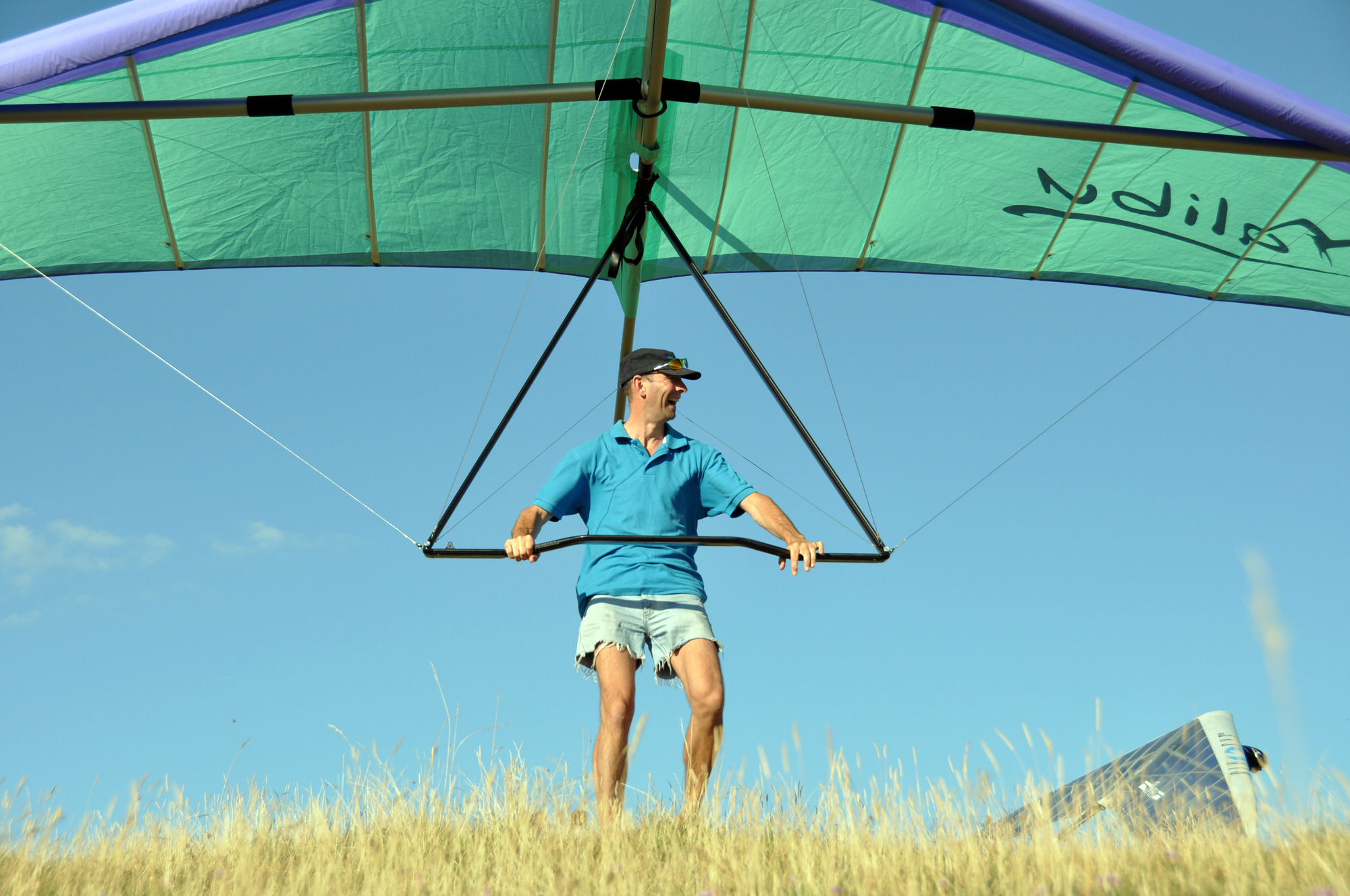


.jpg "Click to enlarge image 20150827_020128 - Joystick parts 1 (made by Ken Hickey).jpg")


 The rib templates are first traced off the original full scale drawings onto grease-proof paper (kitchen baking parchment) before being laid out and taped down on to 1/2" thick Medium Density Fiberboard (MDF) using decorator's paper masking tape, which is easy to remove.
 With the outlines marked out, the internal ribs are now drawn in using a fine tipped pen or pencil.
 The parts are roughly cut out using a jigsaw, taking care not to let the blade wander inside the black marker line.
 Once cut out, the parts are carefully sanded down to the inside of the black marker line using a bench mounted high-speed disc sanding machine.
 Each part is carefully adjusted (by continued sanding) until it perfectly matches the original plans.
 The machine sanding process creates a lot of very fine dust. It is essential to wear a full face breathing mask as the dust and formaldehyde in MDF can cause serious heatlh problems later on in life. Don't take any risks with your health - it's not worth it.
 A general purpose router is equipped with a specially built jig/fence to cut a 5mm deep rebate.
 The width of the rebate can be set by adjusting the depth of the router plunge. The depth of the rib caps and internal struts starts at 24mm at the root rib and is reduced by 2mm at each rib out from the root until rib #8, after which the remaining ribs (#8 to #13) are just 10mm deep.
 The perimeter of the sanded rib mould blanks are routed to form the 5mm deep rib caps. This is a really quick and easy job... very satisfying!
 Here's how the rib mould looks after the perimeter has been routed.
 The router (with it's bespoke base plate jig) is clamped to the work bench... with another small G-clamp gently pressing down on the power button!
 Close-up of the router and jig set-up.
 The rebates for the internal, diagonal struts are cut using the router running against a simple fence pinned to the surface of the MDF.
 Same as above - just from a different direction!
 The finished rib mould - ready for fine sanding and varnishing,
 The rib moulds are fine sanded and given up to five coats of polyurethane gloss varnish to seal the MDF.
  The finished moulds are next laid out on a 1m x 1m square sheet of 5mm thick closed cell PVC foam board, taking care to fit as many parts as possible onto a single sheet of the foam. A ball-point pen is used to trace around each part.
 With the parts traced out on the foam board, a very sharp Stanley knife (craft knife) is used to cut out the parts free-hand. The parts are cut out taking care not to let the knife wander inside the ink perimeter line. Each foam part will be fine tuned to exactly match its host mould later on...
 More rib moulds...
 All the foam rib blanks roughly cut out - note that you can still see the ballpoint pen marks around the perimeter.
 Three or four pieces of double sided sticky tape are used to attach the foam blanks to their respective MDF moulds.
  After trimming with the router, the PVC foam and MDF mould are exactly the same size and shape!
 Once trimmed, the foam is carefully removed from the MDF, taking care not to damage either.
  The next step is to carefully mark in the internal struts. The curved rib caps are easily marked in by gently scoring the foam using an adjustable carpenters gague.
 A very sharp knife is used to cut out the excess foam between the internal struts.
 A useful tool for sanding the foam internal struts so that they fit the mould is a piece of fine emmery paper stuck to a scrap of wood or aluminium strip using double sided sticky tape. This ensures that you can sand the foam perfectly flat and evenly... something not possible if the emmery paper is just loosly held in your fingers!
 The finished foam core, sanded to a perfect (but not excessively tight) fit for the MDF mould.
 Patients, care and attention to detail are rewarded with a perfect set of foam rib cores!
 Don't they look great!


 Cutting the CF cloth at 45
 Infusing one side of the inner leading edge.