Welcome, Guest
Username: Password: Remember me
  • Page:
  • 1
  • 2

TOPIC:

Rudder spar dimensions incorrect on drawing #4 28 Jan 2015 19:20 #877

Are you sure !
Look at drawing 5. There is an offset between center of arc of leadind edge and centrline of the stabilizer rib#6.


you can observe this offset on my drawing ( topics " CD tail dimensions " ).
This is the result of asymmetrical profil...
Also there is an offset between stabilizer and elevator centerline ( it's my deduction )


Attachments:

Please Log in to join the conversation.

Last edit: by Bertrand Botrel.

Rudder spar dimensions incorrect on drawing #4 28 Jan 2015 21:00 #879

Oops! You are absolutely correct Bertrand - and the drawing is in fact correct!

I made the mistake of assuming that the center line of the spar was in fact in the geometrical center... which it is not! I just measured the drawing of Rib #6 carefully and the dimension above the 'center line' is 1 3/32" and just 1" below the line. The base of Rib #6 is also 2 3/32".

What is it they say?... Assumptions are the mother of all screw ups!

I'll remove my 'correction' from the list of errors.

Phil.

Please Log in to join the conversation.

Horizontal Stabiliser Front Spar - Drawing #5 - Incorrect Dimension 17 Mar 2015 15:00 #881

Drawing #5 shows two incorrect dimensions for the widest point on the front spar of the horizontal stabiliser. The drawing of the front spar gives the widest point (at Rib #1) as 4.50", which does not match the dimension of Rib #1 where it is bonded to the spar. Direct measurement of Rib #1 (which is drawn full scale on Drawing #5) reveals that the correct dimension of the spar at this point should be 3 13/16ths". The half-width dimension is also incorrect and should read 1.91" rather than 2.25".


Attachments:

Please Log in to join the conversation.

Last edit: by Phil Lardner.

Elevator Pulley Brackets (Sheet #21) - shown upside down. 21 Nov 2018 00:18 #1211

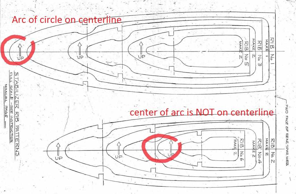
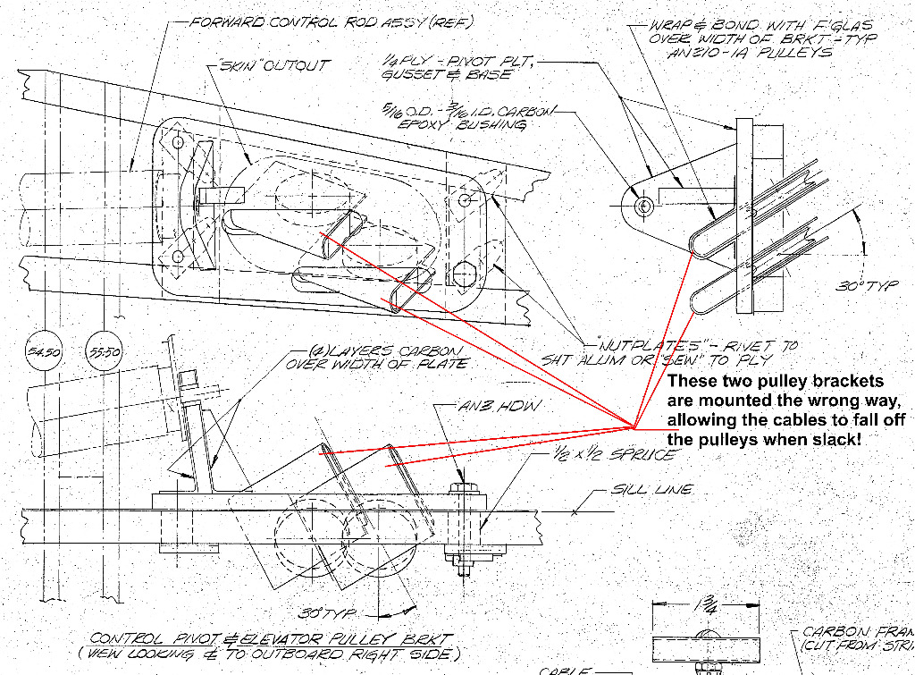
I should have spotted this much earlier, but on Sheet 21, the two Elevator Pulley Brackets are shown mounted upside down. Made to the plans (as I did!) the two elevator cables are able to fall off the pulleys when the cables are slack or loose. This is not a problem as long as the cables are kept under tension, but they must be double checked if you detach the cables for any reason.

The carbon brackets that envelope the pulleys should be mounted the other way up, in such a way as to prevent this problem.


Phil.
Attachments:

Please Log in to join the conversation.

Drawing 15 - Incorrect Centre Line shown on Pilot Pod Template at Station 54.50" 01 Nov 2019 18:46 #1263

Pod Frame Template at 54.50" - the centre line is drawn incorrectly. When the 1/2 template is flipped over on its given centre line, an incorrect part is obtained. The inside bottom of frame-to-centre-line distance should be 8.5" for a 17" wide cockpit width.

Attachments:

Please Log in to join the conversation.

  • Page:
  • 1
  • 2