Welcome, Guest
Username: Password: Remember me
  • Page:
  • 1

TOPIC:

CD tail dimensions and coordinates 15 Jan 2015 08:14 #858

Hi, same work on the stabilizer and elevator. Once again the original drawings are inaccurate.
I had to slighty reduce the depth of the elevator ( CAUTION : original dimension are not respected ). In addition i had to increase Y scale factor ( 4% ) for the whole drawing to match the main spar depth of the stabilizer.


File Attachment:

File Name: CDstabiliz...2015.pdf
File Size:149 KB
Attachments:

Please Log in to join the conversation.

CD tail dimensions and coordinates 15 Jan 2015 12:09 #859

Interesting...

A 4% error seems a lot!

I just checked my set of drawings (prints from the scanned drawings) and my measurements *of* the drawings are a lot closer to the dimensions given *on* the drawings. I can't remember, but I have a feeling that the engineering office that printed out my set of drawings corrected the print scale for each individual drawing before printing them. The print scale errors on my set of drawings are generally under 1% if I recall correctly.

Measuring H-stab Ribs #1 and #6 on my drawings and comparing these dimensions to the indicated spar dimensions gives me a scale error of 1.4% and -1.2% at these two points... which suggests my ability to measure the drawings accurately may be in question... or perhaps the drawings really aren't 100% accurate!

H-stab Rib #1 base = 4 7/16" = 4.4375" = 112.7mm (measured off the drawing #5)
H-stab spar depth at Rib #1 = 4.5" = 114.3mm (dimension given on the drawing #5)
Scale error is 1.4% (112.7 / 114.3 = 0.986 x 100 = 98.6% scale. 100 - 98.6 = 1.4%)

H-stab Rib #6 base = 2 1/8" #5 = 2.125" = 53.975mm (measured off the drawing #5)
H-stab spar depth at Rib #6 = 2.1" = 53.34mm (dimension given on the drawing #5)
Scale error -1.2% (53.975 / 53.34 = 1.012 x 100 = 101.2% scale. 100 - 101.2 = -1.2%)

Averaging the two errors gives me an overall scale error of 0.1%. You'll probably get slightly different numbers depending on the accuracy of your measurements and the thickness of the lines on the drawings... which account for a lot!

In my case, my H-stab rib bases match the spar dimensions almost perfectly because of the way I molded them. The molds were made to exactly match the template drawings and the carbon was formed over them, which means that the outer dimension of the rib flanges are larger by two layers of carbon all round. In the end, *small* errors can be accommodated by using a little extra epoxy + cotton flock mix when gluing ribs to spars.

Phil.

Please Log in to join the conversation.

CD tail dimensions and coordinates 20 Jan 2015 19:22 #861

Hi Phil. After new calculation, i found stabilizer rib#1 lenght at 15,25" ( proportion with stab rib#6 lenght (5")). With this, X/Y ratio error ( with spar depth at 4,50" )is only 1.8%.
My main error was to round the rib#1 lenght at 15".
What is your measure for rib#1 lenght ?

Please Log in to join the conversation.

Last edit: by Bertrand Botrel.

CD tail dimensions and coordinates 26 Jan 2015 12:26 #862

Hi Bertrand,

Sorry for the delay in replying. I measure Rib #1 at 15 3/8" off my set of plans. I then calculated the actual drawing scale to be 24.9375% or 4.01:1 (so, very nearly the 4:1 shown) so I'm happy that my dimensions are acceptable.

I think that as long as you are consistent in applying the same 'error' to all your rib dimensions that you will end up with a perfectly good H-stabiliser. As long as the ribs fit the spar then I think an 1/8th" error in length will make no difference.

If you're creating CAD drawings then you can use Rib #1 and the tip rib as the basis to work out the exact lengths of the other ribs, as the slope is a constant 10 degrees.

Phil.

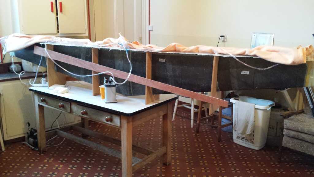
PS - I just infused my H-stab skin this weekend - one layer of carbon + one layer of kevlar. Looks really good!
Attachments:

Please Log in to join the conversation.

  • Page:
  • 1