Welcome, Guest
Username: Password: Remember me

TOPIC:

Progress on Phil Lardner's All-carbon CD? (Part 1) 12 Jun 2015 21:32 #899

Rick,

email me direct here..... This email address is being protected from spambots. You need JavaScript enabled to view it. and we can discuss the time table for the molds return to where you are...then maybe the expense for me to ship them here and back 2U.
The topic has been locked.

Progress on Phil Lardner's All-carbon CD? (Part 1) 01 Jul 2015 00:30 #907

Gus was asking me how I made my trailing edges in a separate email, so I thought I'd detail part of the process here:

Fabricating Trailing Edge Stock

I need to take a few more photos to fully illustrate the process (encapsulating in carbon and vac-bagging) - I'll do that when I get around to making my flaperon trailing edges, but here's a selection of photos showing the steps I took to make my trailing edges.

Training Edge - 1: I cut a number of 1" wide strips of 1/2" thick closed cell PVC foam board using a table saw set at 90deg.


Trailing Edge - 2: The 1" wide strips are stuck to a length of wood using double-sided sticky tape - this gives the rather wobbly foam strips some rigidity for the next step. The table saw blade is now set to the desired angle and the 1" strip is run through the table saw again.


Trailing Edge - 3: This gives your 1" strip a right-angle triangle profile.


Trailing Edge 4: The table saw blade angle is adjusted and the right-angle profiled foam strip is re-positioned on the wooden support and run through the saw again. This turns the right-angle profile into an isosceles triangle. The base of this triangle profile should be 5mm or 1/4" wide, and the height if the triangle should be 3/4"


A number of these strips are glued end-to-end to the desired length and then encapsulated in carbon cloth as follows...
Attachments:
Last edit: by Phil Lardner.
The topic has been locked.

Progress on Phil Lardner's All-carbon CD? (Part 1) 01 Jul 2015 00:40 #908

Fabricating Trailing Edge Stock - contd...


A length (as long as the trailing edge) of 4" x 1.5" wood or MDF is cut to an isosceles triangle profile in the same manner as the foam strips.


Trailing Edge 7: The wooden strip is run through the table saw again to truncate the isosceles triangle. The top of the truncated triangle should be 5mm or 1/4" wide (to match the foam strips.) Image 7 shows the wooden former for the elevator trailing edge, and includes the 10deg bend in the middle!

The wooden former is glued to the work table so that it stands up, and covered in packing tape or other plastic to prevent the epoxy sticking to it.


A 6" wide length of carbon cloth is wet out and laid over the plastic covered wood strip.


The foam core, made earlier, is carefully places on top of the carbon.


The foam core is covered with another (8" wide) layer of carbon cloth.


The whole assembly is vac-bagged down onto the table and left to cure.


Trailing Edge 9: Hey-presto - you now have a continuous length of fully encapsulated foam core trailing edge stock! The image below shows a short off-cut of the trailing edge stock.


I'm really happy with the way these trailing edges turned out. The foam core is encapsulated in just a single layer of carbon cloth, but the flanges that extend from it, which get bonded to the ribs, are two layers thick. You could easily beef this up with an extra layer of cloth but I don't think it's necessary.


Last edit: by Phil Lardner.
The topic has been locked.

Progress on Phil Lardner's All-carbon CD? (Part 1) 19 Aug 2015 11:36 #910

Hello Phil. Please tell me where I can see your full carbon drawings of the CD?

In what system of measurement you made your drawings, only imperial or have the option of drawings in the metric system? Do your drawings specify the brand carbon fiber fabric for every detail? Or you use one brand kabon fabric for all the details? How and from what is material you do spar cap?

I thank you in advance for your answers.

Valerii.
The topic has been locked.

Progress on Phil Lardner's All-carbon CD? (Part 1) 20 Aug 2015 17:14 #911

Hi Valerii,

You can find a set of scanned plans here: carbon-dragon.ihpa.ie/index.php/home-top/plans#full-scale-plans. I'm afraid I haven't created any special plans for my all-carbon CD - I'm just modifying the originals 'on the fly' and trying to document how I'm doing things here in the forum and on my project page. Hopefully the photos I've uploaded tell the story when studied in conjunction with the original plans. That said... feel free to ask as many questions as you like about any part of my build and I'll do my best to help you out.

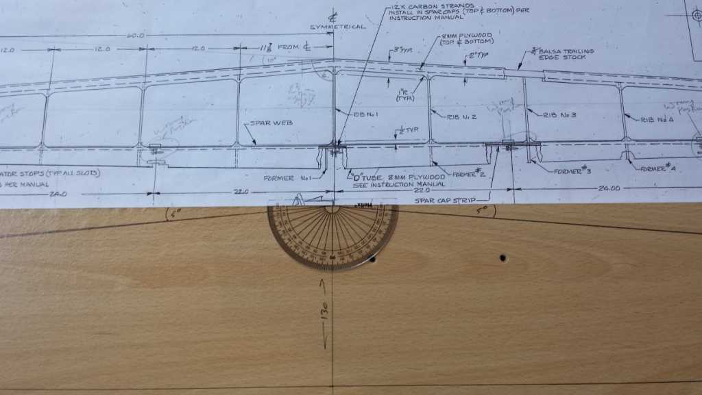
The dimensions given in the original drawings are a curious mixture of imperial and imperial.decimal - in other words, in some places you will see a dimension given as 24 1/2" and in other places as 24.5"! One really glaring error in the dimensions is that they universally refer to '8mm ply' when in fact it should read '0.8mm or 1/32" ply'!! I tend to convert everything to metric (mm) when I am drawing out components like spars directly onto my work table. 1" = 25.4mm.

With the exception of my main wing leading edges, I have used 195gsm 3k twill weave carbon fiber throughout my project. For the tail fin and horizontal stabiliser leading edges, all the spars and the tail boom, this cloth needs to be cut at 45degrees to the axis of the weave to exploit the maximum strength of the cloth. This is a real pain in the bum(!) and if I were starting again, I would source and use a 200gsm bi-axial cloth instead. It would make preparation, cloth cutting and mold lay-up times *much* quicker. Happily I don't think I'll have enough twill cloth to do my main wing leading edges and will order a 400gsm 24k bi-axial cloth for that last big lay-up.

www.easycomposites.co.uk/products/carbon...ll-199gsm-3k-1m.aspx

shop1.r-g.de/item/192400127-EBA

Throughout my project I am using a low viscosity Vacuum Infusion Resin (I'm using the vacuum assisted resin infusion method almost exclusively as it's much safer and much, much more convenient!) The resin is cured at around 25C for 24hrs before being post cured at incremental temperatures over 16 hours up to 80C.

www.easycomposites.co.uk/products/epoxy-...-infusion-resin.aspx

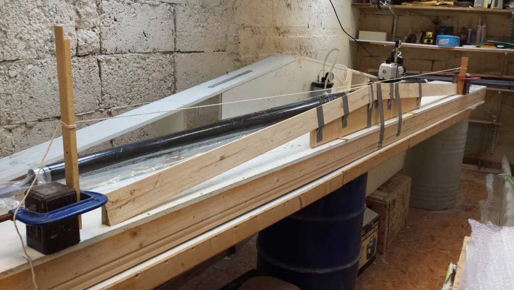
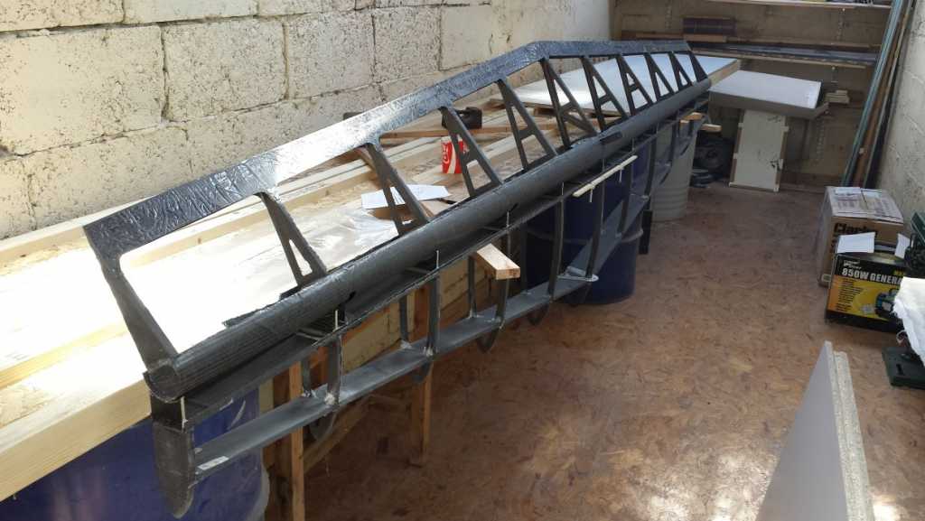
My spars are generally fabricated out of two layers of 195gsm twill carbon cloth, cut at 45deg to the weave. Actually only one layer of carbon cloth is necessary to carry the loads in the spars, but this makes for a very fragile spar which is easily damaged when removing it from the vacuum stack. Two layers makes for a much stiffer and tougher spar. The central, root section of my main wing spar is beefed up a bit with four overlapping layers of cloth between the two #1 ribs - this was partly done for extra strength and partly because it made for a simpler lay-up.

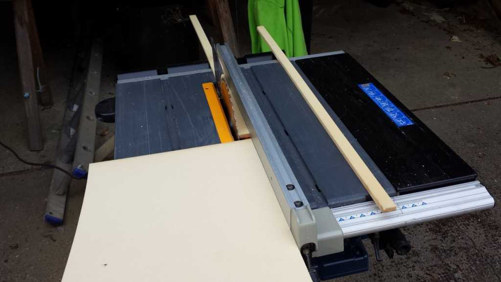
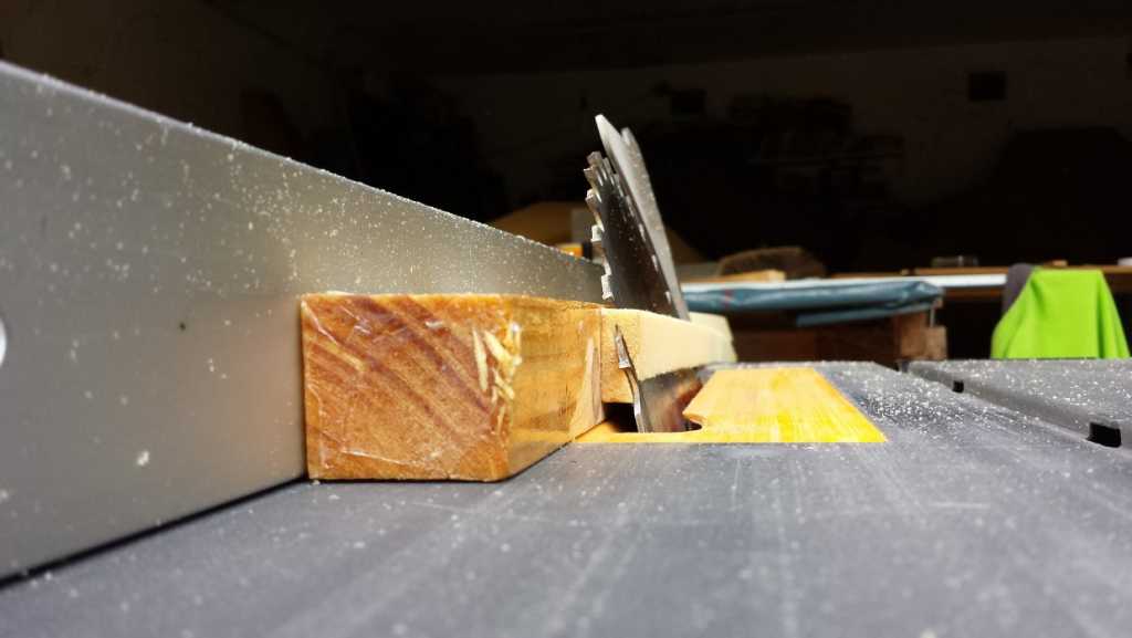
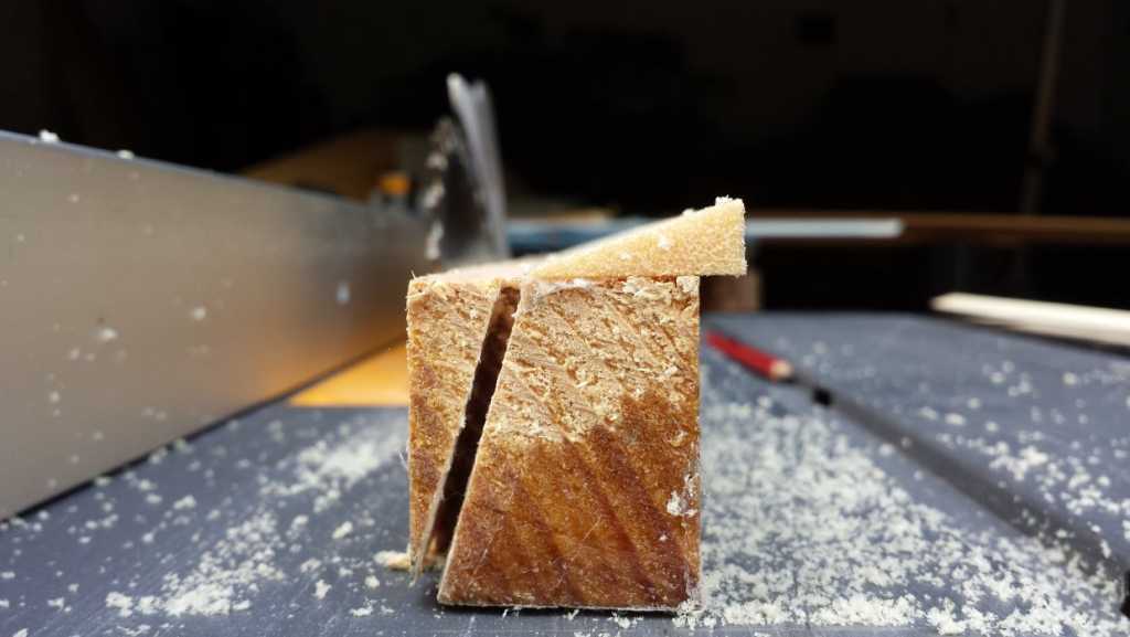
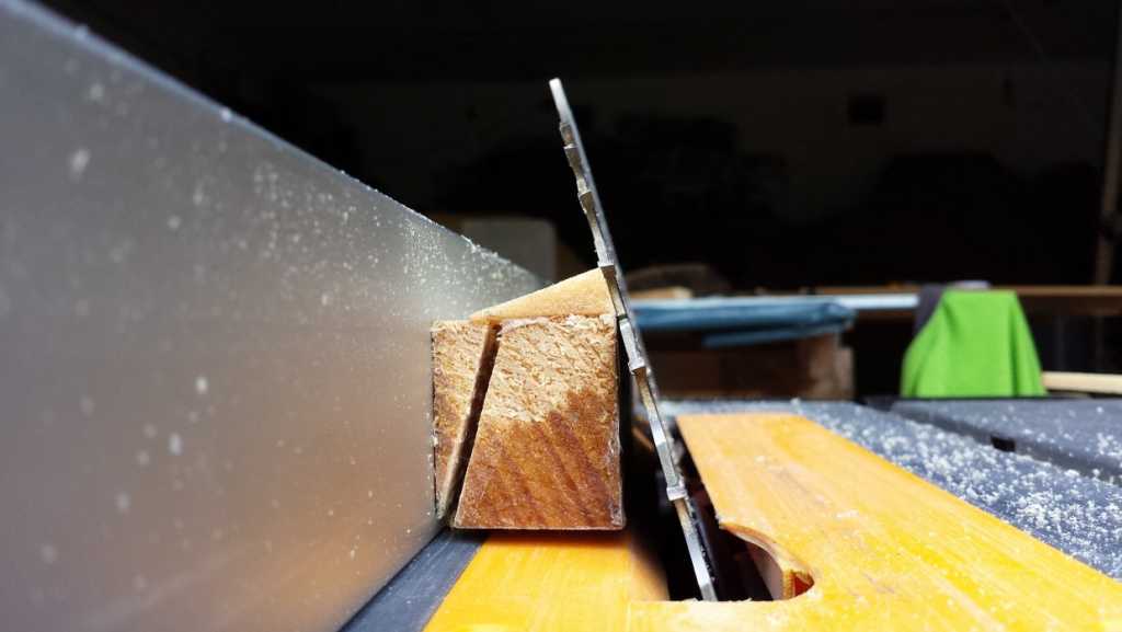
The solid carbon Load Transfer Bars that transfer the loads from the spar to the metal wing connection fittings are encapsulated by a further two layers of 195gsm twill cloth. The LTBs themselves are cut crom a larger panel made up of 24 layers of 195gsm twill cloth cut at 45deg, using a hand, wet lay-up instead of vacuum infusion. My attempts to vacuum infuse 24 layers of cloth resulted in the part being starved of resin in the inner layers. The LTBs are a strength critical part, and you must get them right!! After curing and post curing the 24 layers thick panel, I cut it up into 1" wide strips using a table saw and further bevelled the edges, where necessary, using a bench sanding machine. You can see the details of how the spars are laid up in some of my videos.


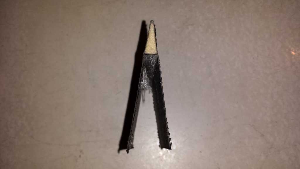
With the exception of my main wing spar, all the other spars have a single 0.092" x 0.22" pultruded carbon rod encapsulated into each edge forming a 10mm-15mm wide spar cap. The main wing has several rods, tapering off as you move further outboard. See my Wing Analysis spreadsheet for details of how many rods I used.

carbon-dragon.ihpa.ie/index.php/cd-build...wing-stress-analysis

www.marskeaircraft.com/carbon-rod-pricing.html

Hope this helps! Feel free to ask questions.

Gotta dash - I've got my last batch of flaperon ribs infusing as I type :-)

All the best,

Phil.

PS - a few more videos to keep you busy!
Phil Lardner's Carbon Dragon Project - 0 - Setting up parts for Vacuum Assisted Resin Infusion.wmv


Phil Lardner's Carbon Dragon Project - 1 - Vacuum Assisted Resin Infusion


Phil Lardner's Carbon Dragon Project - 2 - debagging first batch of ribs


Phil Lardner's Carbon Dragon Project - 3 - Demoulding a part


Phil Lardner's Carbon Dragon Project - 4 - Fabricating Foam Cores.wmv


Phil Lardners Carbon Dragon Project 5 Shaping the Leading Edge Moulds


Phil Lardner's Carbon Dragon Project - 6 - Covering the Leading Edge Foam Plug in Fiberglass


Phil Lardner's Carbon Dragon Project - 7 - Shaping the Outer Leading Edge Foam Plug
i.ytimg.com/vi/pWvJ-G4D0do/mqdefault.jpg

Phil Lardner's Carbon Dragon Project - 8 - Infusing the Tail Boom Skins


Phil Lardner's Carbon Dragon Project - 9 - Rib Trimming


Phil Lardners Carbon Dragon Project 10 Infusing the Horizontal Stabiliser Skin


Phil Lardner's Carbon Dragon Project - Trimming the Horizontal Stabiliser Front Spar


Phil Lardners Carbon Dragon Project - Bonding the Tail Boom Halves Together


Phil Lardner's Carbon Dragon Project - Laying the up Main Wing Spar center section


Phil Lardner's Carbon Dragon Project Schempp Hirth Air Brake Prototype
The following user(s) said Thank You: Valerii Ivantsov
Last edit: by Phil Lardner.
The topic has been locked.

Progress on Phil Lardner's All-carbon CD? (Part 1) 22 Aug 2015 06:04 #912

Hello Phil.

You puzzled me, I is not bad at doing different things with my hands and I like it. But I need detailed instructions if I do not know thoroughly the theoretical basis of the product.

Aerodynamics refers to areas of knowledge where I imagine everything in general but did not venture to make of calculations. According to this when I start to build a CD I will have a lot of questions for you, and as a result you will make a very detailed instructions for the construction of a CD for the "dummies."

So far, only one question for the workout.

When you paste the rib layers carbon fibre glued outside parts. Removing carbon fibre cutter you left inside a closed loop ribs slightly carbon fibre outside ribs inside these residues do not interfere with anything, and even make the piece stronger mechanically. But the outer contour of the excess carbon fibre be milled flush, otherwise it will be broken airfoil ribs. As a result, the outer contour of the rib layers carbon fibre remain glued together? Or something I did not notice and did not understand and I am mistaken?

Thank you very much for your detailed answer.

Valerii.
The topic has been locked.